Lidded vessel

a technology of a ring and a ring body, which is applied in the field of lidded vessels, can solve the problems of user stress and slight increase in force expenditure, and achieve the effects of reducing the wall thickness, and reducing the coefficient of sliding friction of the sliding ring

Inactive Publication Date: 2007-06-07
EPPENDORF AG
View PDF18 Cites 14 Cited by
  • Summary
  • Abstract
  • Description
  • Claims
  • Application Information

AI Technical Summary

Benefits of technology

[0025] According to a further embodiment, an initial sliding of the sliding ring on the insertion region and subsequent placing of the retaining ring on the retaining region is promoted by the hollow stopper bearing in the sealed position against the front face against an axial stop of the inner wall of the vessel and the retaining ring being a region of the hollow stopper able to be axially compressed by further pressing-in of the lid and able to be laterally pushed outwards radially until sealingly bearing against the retaining region. Preferably, the region of the hollow stopper which may be laterally pushed outwards has a reduced wall thickness and/or is of film-like configuration, so that it may be laterally pushe...

Problems solved by technology

In principle, therefore, the force expenditure slightly increases but this subjects the user to very little s...

Method used


Image

  • Lidded vessel
  • Lidded vessel
  • Lidded vessel

Examples


Embodiment Construction

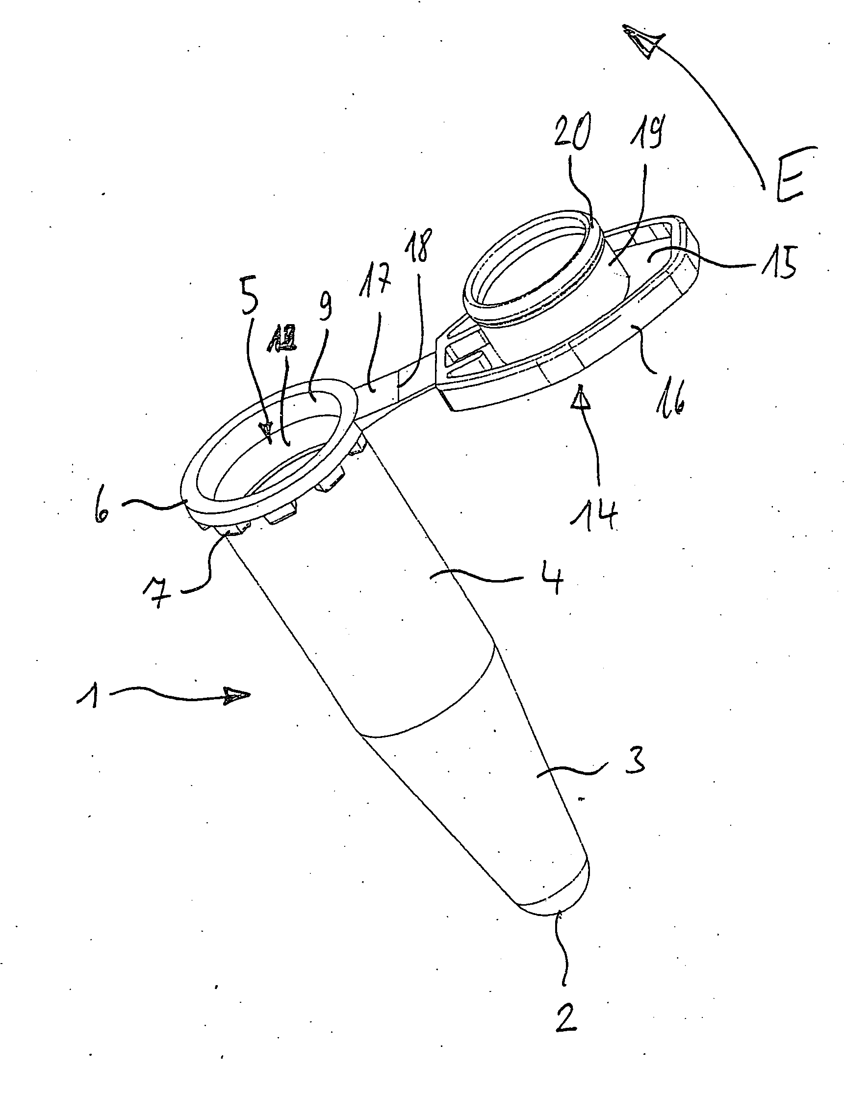
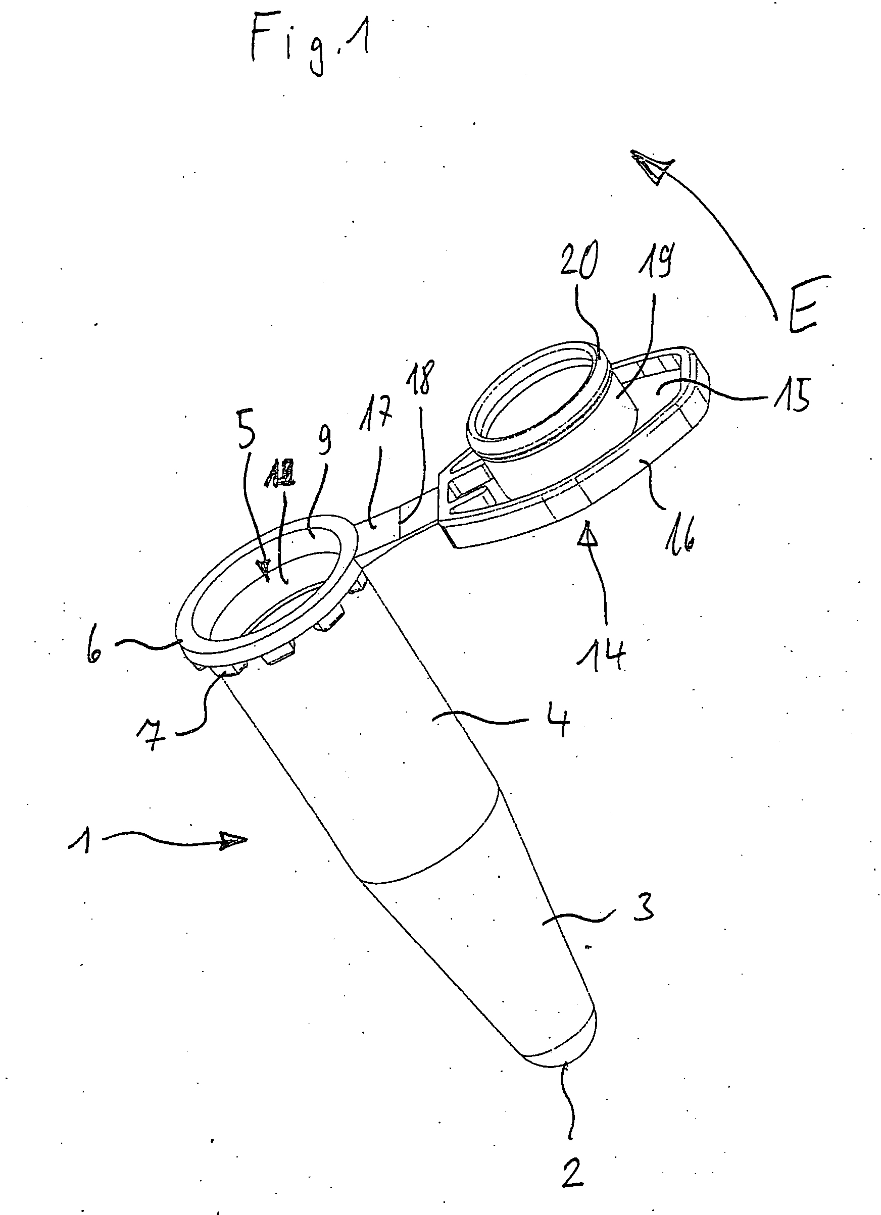
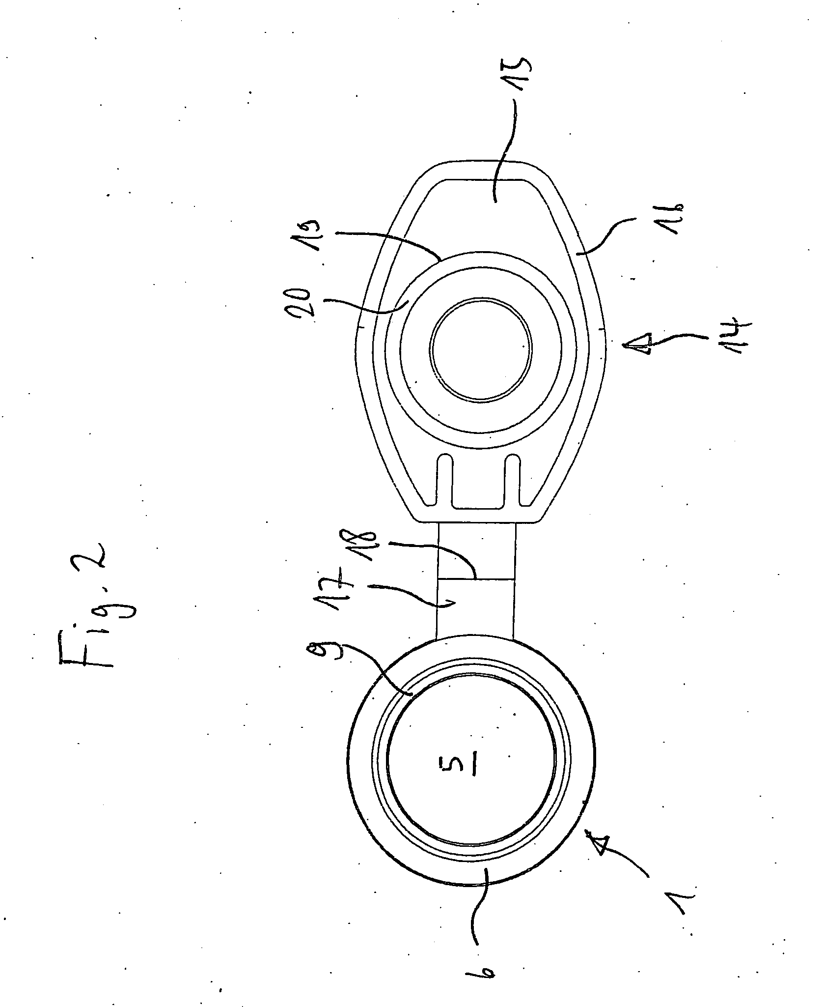
[0047] While this invention may be embodied in many different forms, there are described in detail herein a specific preferred embodiment of the invention. This description is an exemplification of the principles of the invention and is not intended to limit the invention to the particular embodiment illustrated The lidded vessel has a vessel 1 with a shell-shaped vessel base 2, an adjacent conical portion 3 and a cylinder portion 4 adjacent thereto, which comprises a vessel opening 5 and a vessel flange 6 surrounding said opening. In the region of the vessel opening 5, the vessel 1 is reinforced by ribs 7 which are located beneath the vessel flange 6 on the outer periphery of the cylinder portion 4.

[0048] On its inner wall 8 adjacent to the vessel opening 5, the vessel 1 has a conical insertion region 9 which gradually widens towards the vessel opening 5.

[0049] In the region of the smallest diameter, the insertion region 9 has a cylindrical end region 10. The insertion region 9 i...


PUM


Abstract

Lidded vessel made from resilient plastics for laboratory use with a tubular vessel which has a vessel base at one end, a vessel opening at the other end, a retaining region on the inner wall of the vessel and an insertion region between the vessel opening and the retaining region, a lid which has a lid base and a stopper on one side of the lid base and which may be inserted through the vessel opening into a sealing position in the vessel, in which a sealing region of the stopper is placed on a sealing seat on the inner wall of the vessel, and a sliding ring and a retaining ring on the periphery of the stopper, the sliding ring having a lower coefficient of sliding friction relative to the insertion region than the retaining ring has relative to the retaining region and, when mounted, slides over the insertion region and is placed in the sealed position of the retaining ring on the retaining region.

Description

CROSS-REFERENCE TO RELATED APPLICATIONS [0001] Not applicable. STATEMENT REGARDING FEDERALLY SPONSORED RESEARCH [0002] Not applicable. BACKGROUND OF THE INVENTION [0003] Lidded vessels of the aforementioned type typically have a capacity of several tens of millilitres or several millilitres or less than one millilitre. [0004] A known lidded vessel comprises a vessel and a lid with a lid base which, on one side, comprises a stopper with a sealing bead on the periphery. The lid is inserted with the hollow cylinder in the manner of a stopper into the vessel opening, in order to seal the inner wall of the vessel with the sealing bead (DE-A-19645892) the entire contents of which are incorporated herein by reference. [0005] In the known lidded vessels, the closure force for closing the lid is high. This is because the sealing bead has to be pressed with a high surface pressure against the inner wall of the vessel in order for the lidded vessel to be securely sealed. This is, in particular...

Claims


Application Information

Patent Timeline
IPC IPC(8): B01L3/00
CPCB01L3/50825B01L2200/0689B01L2300/042B01L2300/043B01L2300/123B01L2300/16
Inventor LOHN, JURGEN
Owner EPPENDORF AG
Why Eureka
Try Eureka