
Apparatus for thermal simulation of fuel cell

a fuel cell and thermal simulation technology, applied in the field of thermal simulation apparatus, can solve the problems of increasing energy cost, requiring the most challenging technology among the fuel cells, and increasing the price of energy, so as to save costs

Inactive Publication Date: 2007-06-07
INST NUCLEAR ENERGY RES ROCAEC
View PDF9 Cites 6 Cited by
  • Summary
  • Abstract
  • Description
  • Claims
  • Application Information

AI Technical Summary

Benefits of technology

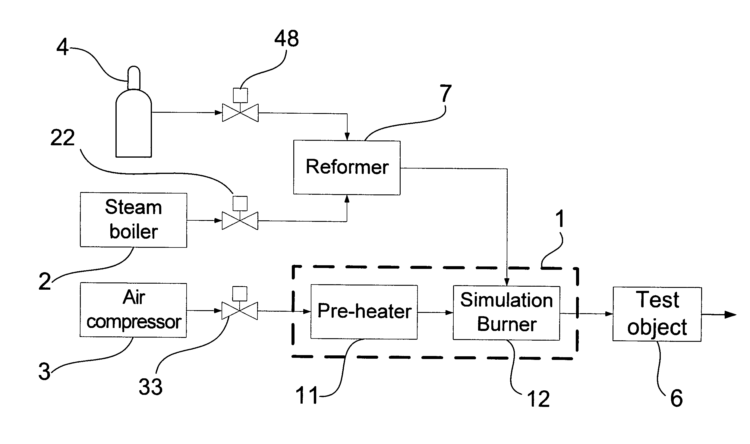
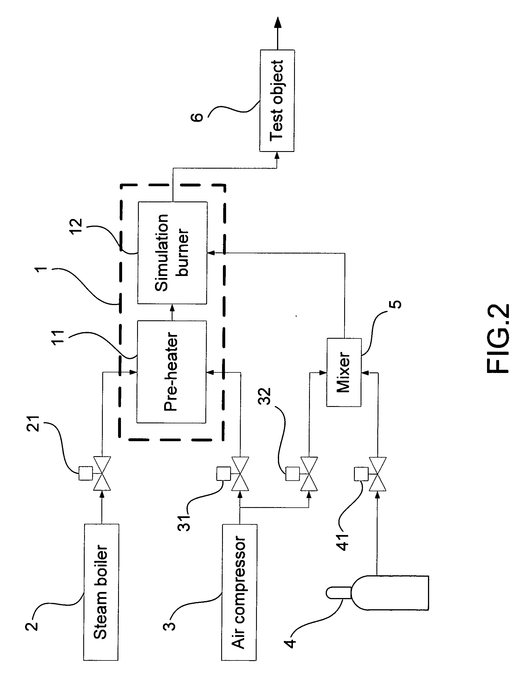
[0005] The main purpose of the present invention is to test a sequential burner, a heat exchanger and / or other component by using a pre-heater and a simulation burner coordinated with a steam boiler, an air compressor, a gas supplier, a mixer and a reformer, where a SOFC is replaced to save cost when running initial system integration tests of the SOFC.

Problems solved by technology

As the price of energy is getting higher, energy expense has become a big issue in the world nowadays.
Yet, since it is run under a high temperature and the exhaust gas it produces is of high temperature too, it requires the most challenging technology among the fuel cells as well.
Nevertheless, a SOFC costs high and its structure is not strong, even weak with its main body, it does not sustain a severe operation or environment.
Obviously, owing to its high cost, when the environment has a somewhat big change, a high loss might happen, which is not suitable in initial system integration tests.
Hence, the prior art does not fulfill users' requests on actual use.

Method used


Image

  • Apparatus for thermal simulation of fuel cell
  • Apparatus for thermal simulation of fuel cell
  • Apparatus for thermal simulation of fuel cell

Examples


Embodiment Construction

[0014] The following description of the preferred embodiments are provided to understand the features and the structures of the present invention.

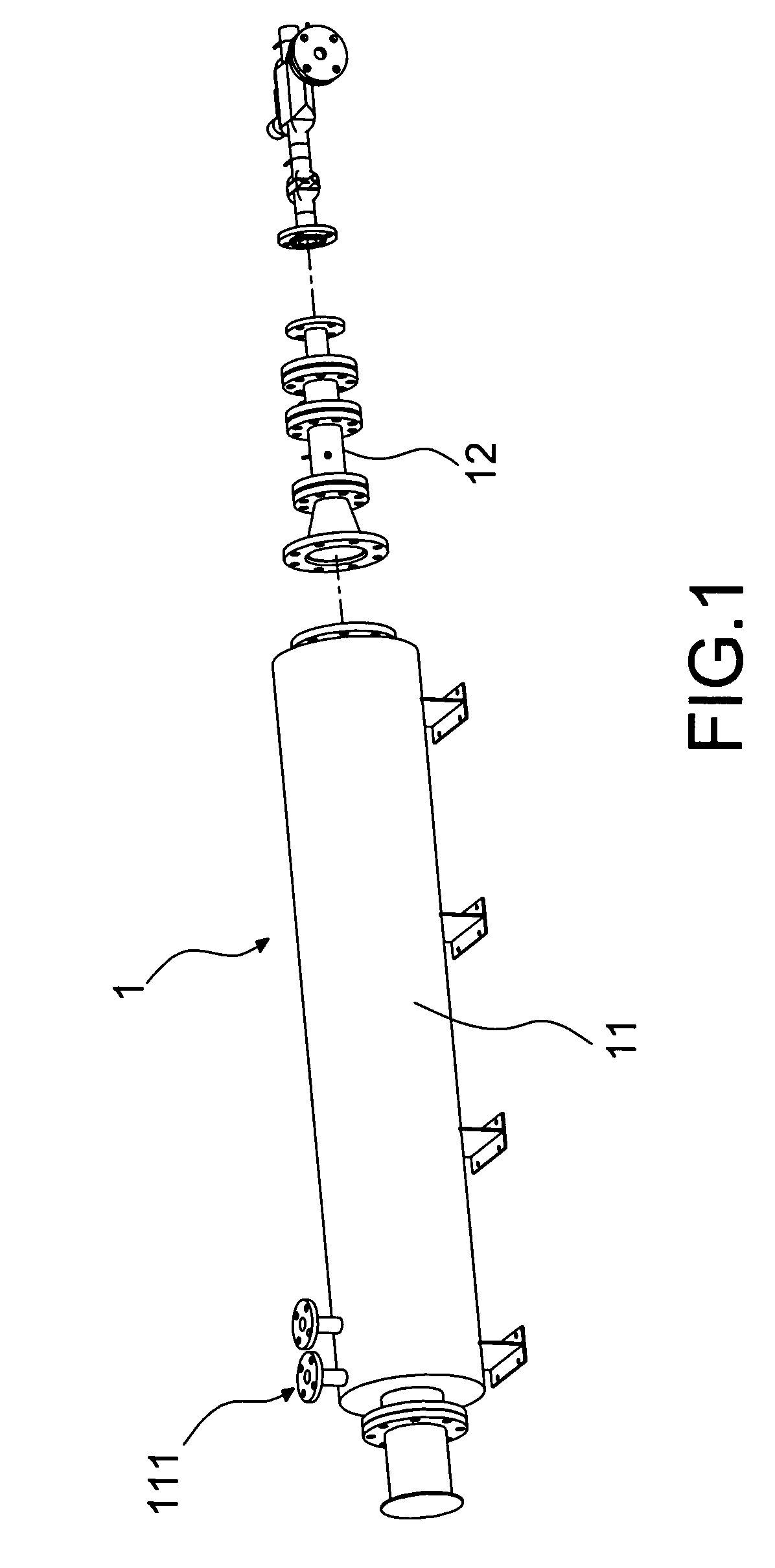
[0015] Please refer to FIG. 1, which is an explosive view showing a fundamental structure of a first preferred embodiment according to the present invention. As shown in the FIG. 1, the present invention is an apparatus for a thermal simulation of fuel cell, where a thermal simulator 1 comprises a pre-heater 11 and a simulation burner 12 and the thermal simulator 1 plays a role as a solid oxide fuel cell (SOFC) where a component is tested with saved costs in initial system integration tests of the SOFC.

[0016] The pre-heater 11 heats an air flow passing by until a predestined temperature between 400 and 600° C. (Celsius degree) to supply heat so that a required temperature is obtained at an end of the simulation burner 12; the pre-heater 11 heats the air flow with an electric heater; and a plurality of inlet pipes 111 are deposed on the p...


PUM


Abstract

The present invention is a simulator used in initial system integration tests of a SOFC to test peripheral components with saved costs by replacing the costly SOFC with the simulator.

Description

FIELD OF THE INVENTION [0001] The present invention relates to a thermal simulation apparatus; more particularly, relates to running initial system integration tests of a solid oxide fuel cell (SOFC) with reduced cost by replacing the SOFC with the apparatus. DESCRIPTION OF THE RELATED ART [0002] As the price of energy is getting higher, energy expense has become a big issue in the world nowadays. Methods for improving energy utilization efficiency are surely the most instant solutions. As is well-known, a fuel cell generates electric power through electrochemical reaction of hydrogen and oxygen, whose power-generating efficiency possesses high potential to all kinds of power-generating technology, from a small electric power used in 3C products to a mega-watt-scaled electric power produced by a power plant. Among all kinds of fuel cells, SOFC shows the best efficiency. Yet, since it is run under a high temperature and the exhaust gas it produces is of high temperature too, it requi...

Claims


Application Information

Patent Timeline
IPC IPC(8): H01M8/04
CPCH01M8/04022H01M8/04037Y02E60/50
Inventor TSAI, YU-CHINGCHYOU, YAU-PIN
Owner INST NUCLEAR ENERGY RES ROCAEC
Learn More