
Swivel device for improved surgical smoke evacuation

a technology of swivel apparatus and smoke evacuation, which is applied in the field of swivel apparatus, can solve the problems of obstructing airflow, affecting and affecting the safety of patients, so as to increase the applicability of swivel apparatus

Inactive Publication Date: 2007-06-07
COSMESCU IOAN
View PDF27 Cites 60 Cited by
  • Summary
  • Abstract
  • Description
  • Claims
  • Application Information

AI Technical Summary

Benefits of technology

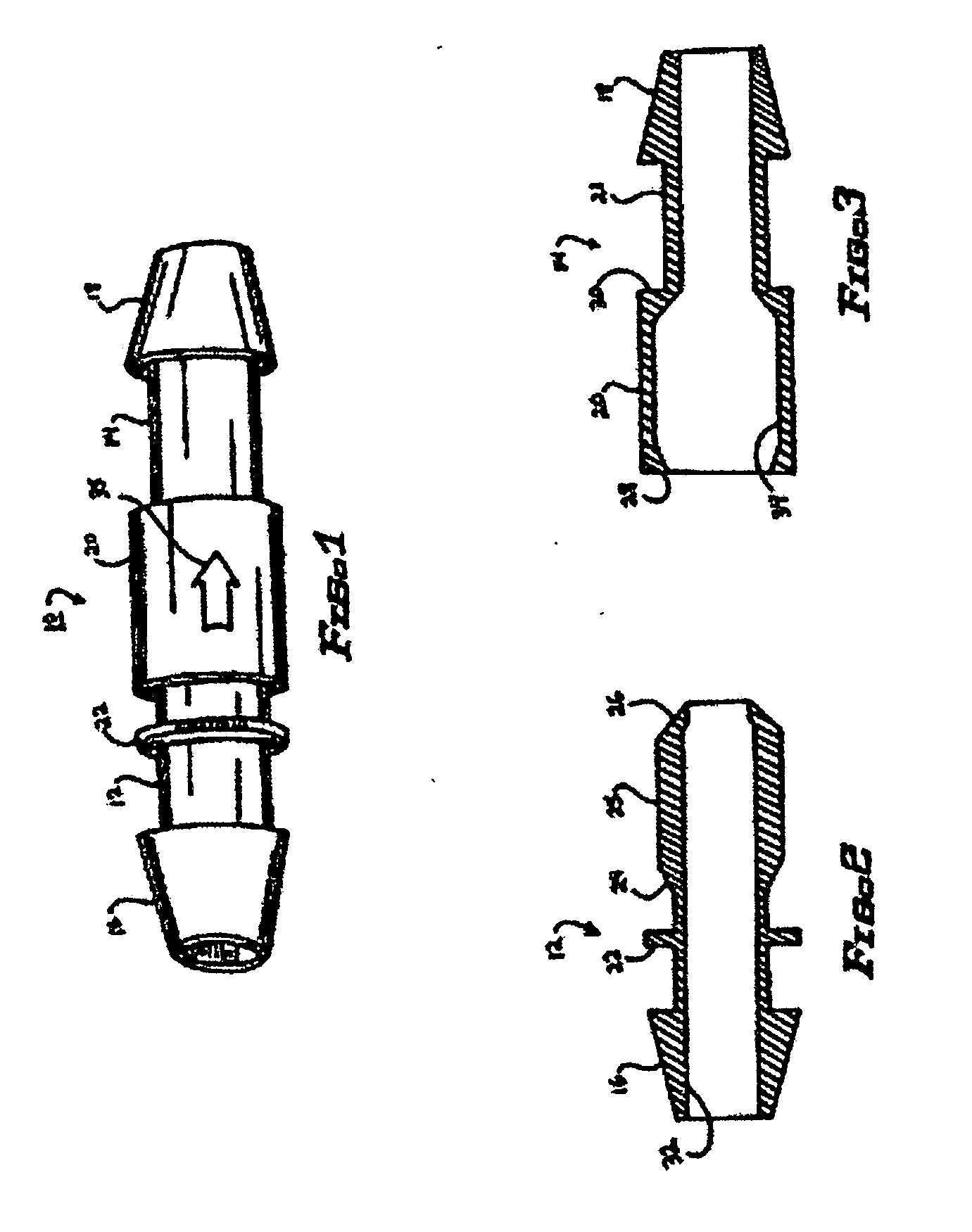
[0007] Furthermore, the extreme proximal end of the fixed member is slightly inverted. This circumferential inversion fits directly against a circumferential inversion near the lengthwise center of the rotating member. When a vacuum is applied, via the vacuum tube, this inverted surface creates an increased vacuum force which presses the inverted proximal end of the fixed member against the inverted center of the rotating member, creating a virtually airtight seal. This seal prevents leakage of air from the swivel apparatus and, thus, maintains the power and efficiency of the vacuum.
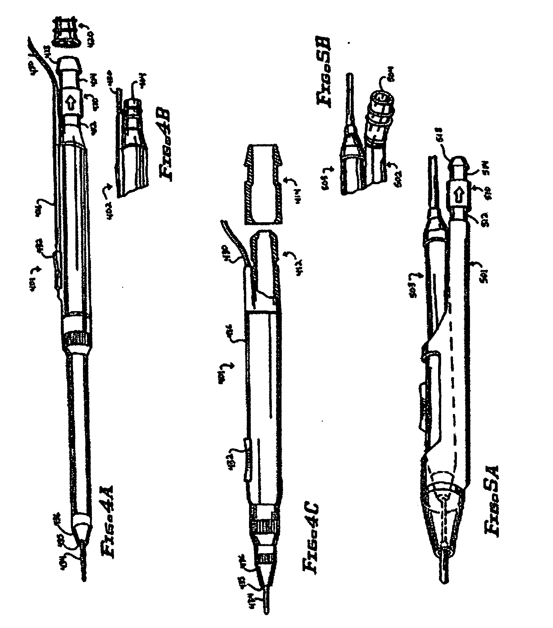
[0009] To increase the applicability of the swivel apparatus, the fixed swivel means may be a separate piece that is attachable to an ESU pencil integrated smoke evacuation system or smoke evacuation shroud attachment and it may also be a permanently incorporated part of an ESU pencil integrated smoke evacuation system or smoke evacuation shroud attachment.

Problems solved by technology

This became cumbersome in many surgical procedures, because two hands were required—one operating the ESU pencil and the other holding the suction device—and because the suction wand often obscured the surgeon's view of the surgical field.
Built-in or attachable smoke evacuation devices have also proved problematic, however.
This twisting of the ESU pencil is problematic in delicate surgical procedures and often requires the surgeon to stop frequently to uncoil the tubing.
However, this tubing is either too soft, so that it collapses under suction, or too narrow, so that it obstructs airflow.
These various problems with vacuum tubing have led many surgeons to not use built-in or attached smoke evacuation devices on ESU pencils.
But the only alternative is the separate suction wand, which is often too cumbersome or visually obstructing.

Method used


Image

  • Swivel device for improved surgical smoke evacuation
  • Swivel device for improved surgical smoke evacuation
  • Swivel device for improved surgical smoke evacuation

Examples


Embodiment Construction

[0019] The present invention is directed to a swivel device for attachment to or incorporation with an electro-surgical (ESU) pencil smoke evacuation system. With reference to the drawings, FIGS. 1, 2 and 3 depict one embodiment of a swivel device 10 for attachment to an ESU pencil with an integrated smoke evacuation system 402, as shown in FIG. 4B, or to a smoke evacuation shroud attachment for an ESU pencil 502, as shown in FIG. 5B. FIG. 4B depicts the proximal end of one embodiment of an ESU pencil 402 with an integrated smoke evacuation system. FIG. 5B depicts the proximal end of another embodiment of an ESU pencil 503 with a smoke evacuation shroud attachment 502.

[0020] The swivel device 10 comprises a fixed member 12 and a rotating member 14. FIG. 1 shows a perspective view of an assembled swivel device 10, with fixed member 12 and rotating member 14. FIGS. 2 and 3 show cross-sectional views of the fixed member 12 and the rotating member 12 of the swivel device 10, respective...


PUM


Abstract

A swivel device includes an improved connection between an electro-surgical unit (ESU) pencil's smoke evacuation system and a vacuum tube. The swivel device includes a fixed member attached to a rotating member. The rotating member allows the stiff vacuum tube to twist and coil freely while preventing forced movement of the fixed member or the ESU pencil. The swivel device can be added to existing ESU pencils with smoke evacuation systems or it can be built into ESU pencils with smoke evacuation systems.

Description

CROSS-REFERENCE TO RELATED APPLICATIONS [0001] This application is related to patent application Ser. No. 08 / 500,045, filed Jul. 10, 1995, now U.S. Pat. No. 5,693,044, which is a continuation-in-part of application Ser. No. 07 / 989,238, filed Dec. 11, 1992, now abandoned.FIELD OF INVENTION [0002] The present invention relates generally to a swivel apparatus. More specifically, the present invention relates to a swivel apparatus for attachment to or incorporation with the smoke evacuation system of an electro-surgical unit (ESU) pencil, and methods therefore. DESCRIPTION OF THE RELATED ART [0003] The use of ESU pencils for cutting tissue and coagulating blood vessels in surgical procedures is well known. When an ESU pencil is used for cutting or coagulation, smoke is produced. In the past, when a surgeon wanted to evacuate this smoke from the surgical field, the surgeon or an assistant had to hold a plastic suction wand, connected to vacuum tubing, near the site of smoke production. T...

Claims


Application Information

Patent Timeline
IPC IPC(8): A61M37/00A61B18/18
CPCA61B18/1402A61B2218/008A61M39/1055A61B18/00
Inventor COSMESCU, IOAN
Owner COSMESCU IOAN
Learn More