
Electrode System For Neural Applications

a neural application and electrode system technology, applied in the field of implanting electrodes in the brain, can solve the problems of additional brain damage, undesirable, and some degree of risk, and achieve the effect of preventing inference of the drive mechanism

Inactive Publication Date: 2007-06-07
YOUNIS IMAD
View PDF25 Cites 155 Cited by
  • Summary
  • Abstract
  • Description
  • Claims
  • Application Information

AI Technical Summary

Benefits of technology

[0010] A broad aspect of some embodiments of the invention relates to electrode designs, algorithms and / or apparatus which allow for relatively rapid and / or exact determination of electrode placement in the brain. Alternatively or additionally, less skill is required of an operator, for performing an implantation. It should be noted that in some embodiments of the invention, the use of the methods and apparatus described herein does not necessarily result in faster and / or better results.
[0011] An aspect of some embodiments of the invention relates to neural electrode leads including a plurality of electrodes that are arranged around a circumference of a lead and have a limited angle of sensing. Optionally, at least some of the thus radially localized electrodes are radially displaced from each other. Alternatively or additionally, at least some of the electrodes are axially displaced from each other. In an exemplary embodiment of the invention, the localized electrodes each comprises bi-polar electrodes, for example, an outer electrode with an associated inner electrode. In some embodiments of the invention, the electrode body is rotatable and / or axially moveable to provide multiple localized measurements of a volume. In an exemplary embodiment of the invention, the multiple measurements are used to assist in more rapidly find a desired stimulation location.
[0012] Optionally, the lead is guided using a stylet to maneuver a tip of the lead, rather than retracting the whole length of the lead. In an exemplary embodiment of the invention, manipulating the stylet will affect a plurality of sensing electrodes at a time. In an exemplary embodiment of the invention, such a stylet is used to allow side motions to reduce at least part of the time expended on trans-axial motions of the lead.

Problems solved by technology

This insertion typically causes some brain damage.
If the electrode is incorrectly placed, it is retracted and then reinserted, typically causing additional brain damage.
The accumulated damage, while not fatal, is generally undesirable and poses some degree of risk.

Method used


Image

  • Electrode System For Neural Applications
  • Electrode System For Neural Applications
  • Electrode System For Neural Applications

Examples


Embodiment Construction

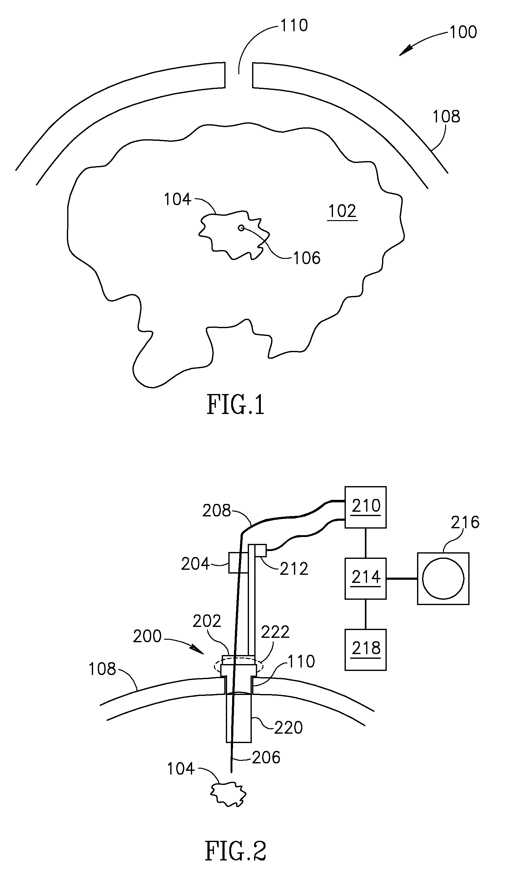
[0073]FIG. 1 is a schematic showing of a body portion 100 including a brain 102. An electrode is to be positioned at a location 106 in the brain, for example, in order to effect treatment or take measurements. In an exemplary procedure, an electrode (not shown) is advanced through an opening 110 (e.g., a bore hole) in a skull 108, to a brain region 104 that includes location 106. Typically, brain region 104 is detected on medical images of the patient. This detection is used to plan the location of opening 110 and the trajectory of the electrode. Typically, however, the exact position of location 106 cannot be determined from the images, being functional in nature, or even if it can be determined, is difficult to aim for. Thus, a search procedure is used to find location 106.

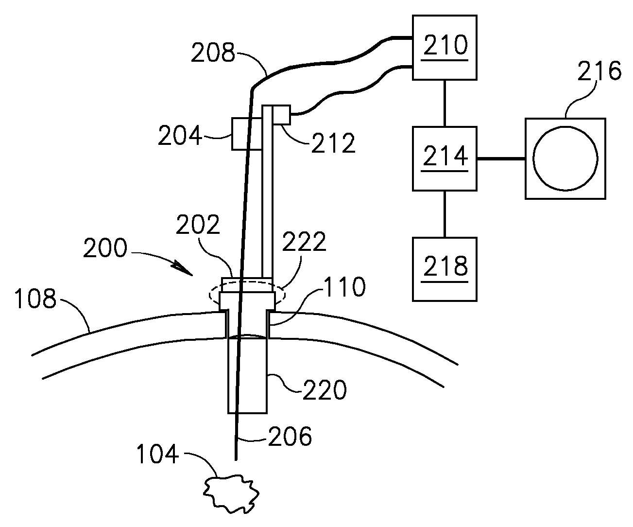
[0074]FIG. 2 is a schematic sectional view of a micro-drive tap 200 for advancing electrode leads in accordance with an exemplary embodiment of the invention.

[0075] In the embodiment shown tap 200 is attached ...


PUM


Abstract

Methods and apparatus for positioning electrodes in a skull. In some embodiments of the invention multiple measurements are made and a desired location is determined or estimated from the results of the measurements.

Description

RELATED APPLICATIONS [0001] The present application is a continuation of U.S. patent application Ser. No. 10 / 491,259, filed Mar. 30, 2004, which is a U.S. national application of PCT Application No. PCT / IL02 / 00796, filed on Sep. 30, 2002, the disclosure of which is incorporated herein by reference.FIELD OF THE INVENTION [0002] The present invention relates to the field of implanting electrodes in the brain, for temporary and / or permanent applications. BACKGROUND OF THE INVENTION [0003] Electrodes are implanted deep into the brain for various reasons. One of the newer applications is implanting electrodes in motor regions of a patient to overcome at least some of the symptoms of Parkinson's disease. Other applications include monitoring epilepsy and / or estimating the effects of anticipated brain surgery. [0004] A typical implantation process is long, for example an hour or two or longer and requires at least one skilled technician in addition to a physician. In the typical implantati...

Claims


Application Information

Patent Timeline
IPC IPC(8): A61N1/32A61BA61NA61N1/05
CPCA61N1/0534A61N1/0539
Inventor YOUNIS, IMAD
Owner YOUNIS IMAD
Learn More