Wide width lock and fold laminate

a wide width and lock technology, applied in the field of flooring, can solve problems such as loss of desired friction, and achieve the effect of increasing the force for disengagement of panels

Inactive Publication Date: 2007-06-14
ARMSTRONG WORLD INDUSTRIES
View PDF8 Cites 140 Cited by
  • Summary
  • Abstract
  • Description
  • Claims
  • Application Information

AI Technical Summary

Benefits of technology

[0008] The present invention overcomes this problem by controlling the friction between the short edges of adjacent installed laminate panels. The friction is small enough to permit easy installation, i.e. requiring a minimum of pressure near the short edge during installation to engage the coupling parts, while being sufficiently great to deter disengagement during normal use when the installed panel is step on near the short end. However, the structure of the present lock and fold edge permits the laminate panels to be disengaged and reassembled, at least a number of times, without permanent damage to the lock and fold edges resulting in the loss of the desired friction.
[0010] In another embodiment, the projection can have a flat surface parallel to the upper surface of the laminate on the side of the projection toward the upper decorative surface and a curved surface opposite the flat surface. The curved surface reduces the pressure necessary to engage the short ends of the laminate panels and the flat surface, which engages a corresponding flat surface in the surface of the corresponding second side edge, increases the pressure necessary to disengage the panels.
[0014] In one embodiment, one or more of the surfaces perpendicular to the upper surface of the laminate panel may have an “S-shaped” or double-curved profile. If the double-curved profile intersects the upper or lower surfaces of the laminate, it may be beveled to deter damages as the panels are engaged.
[0015] Other profiles are also shown. The key features in some embodiments are that at least one pair of the corresponding surfaces of second two opposed edges are perpendicular to the upper surface and the corresponding perpendicular surfaces are non-planar, whereby one of the corresponding surfaces engages the other corresponding surface and the pressure to engage and disengage the laminate panel is increased slightly. In other embodiments corresponding surfaces parallel to the upper decorative surface have features that increase the force to disengage the panels. One of ordinary skill in the art can determine, without undue experimentation, the dimensions and tolerances necessary to permit easy installation, while deterring disengagement during normal use.

Problems solved by technology

However, the structure of the present lock and fold edge permits the laminate panels to be disengaged and reassembled, at least a number of times, without permanent damage to the lock and fold edges resulting in the loss of the desired friction.

Method used


Image

  • Wide width lock and fold laminate
  • Wide width lock and fold laminate
  • Wide width lock and fold laminate

Examples


Embodiment Construction

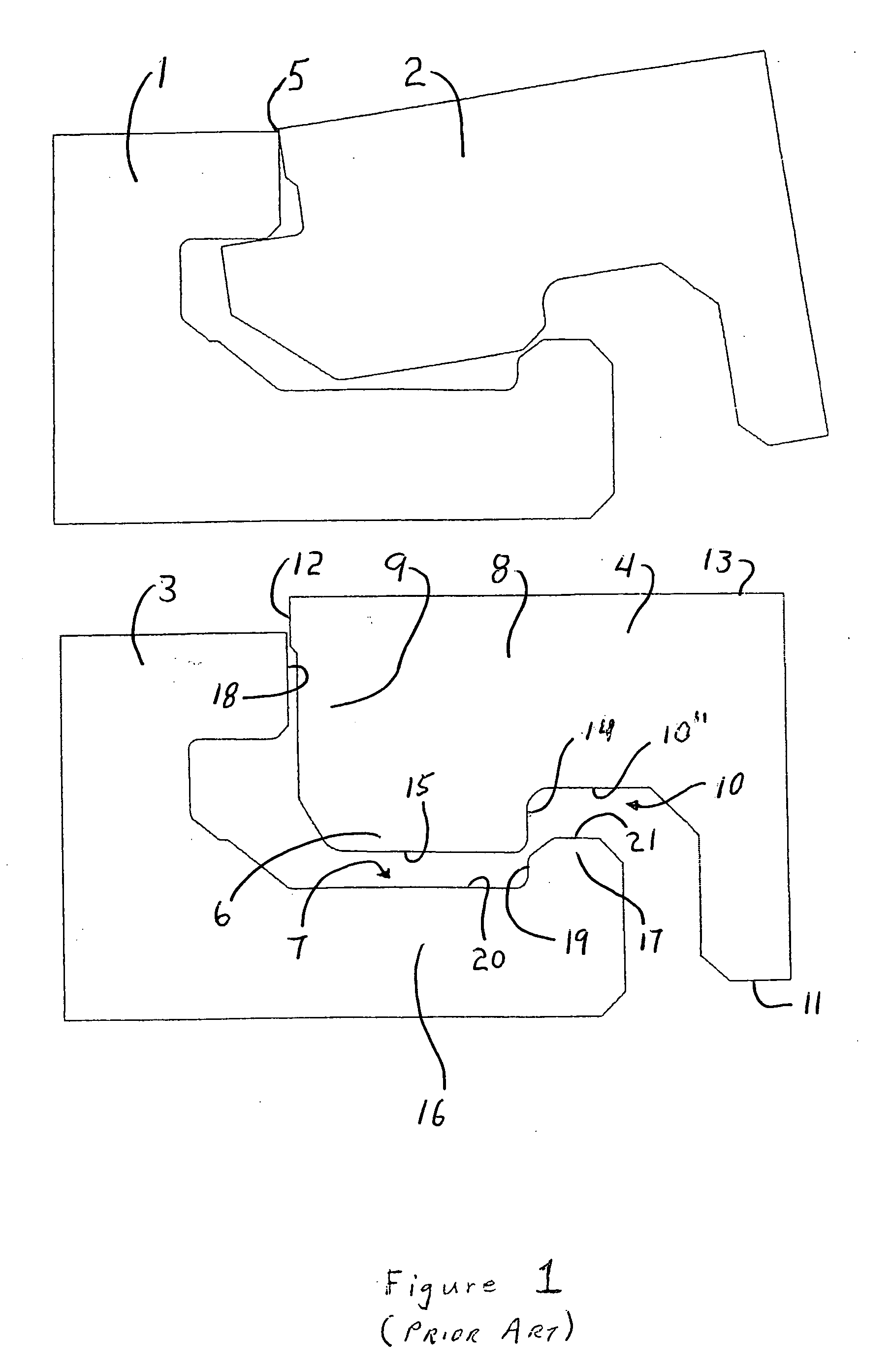
[0037]FIG. 1 shows the lock and fold profile of the prior art. The opposite long edges had the standard locking profile as shown on panels 1 and 2 in FIG. 1. The other two short opposite edges are shown on panels 3 and 4 in FIG. 1. These lock and fold panels were installed by angling a long locking edge of panel 2 into a previously installed row of panels such as panel 1. Panel 2 is then rotated about the contact point 5 between panels 1 and 2, thereby dropping or locking the locking projection 6 of short side into the locking groove 7 in the other short side.

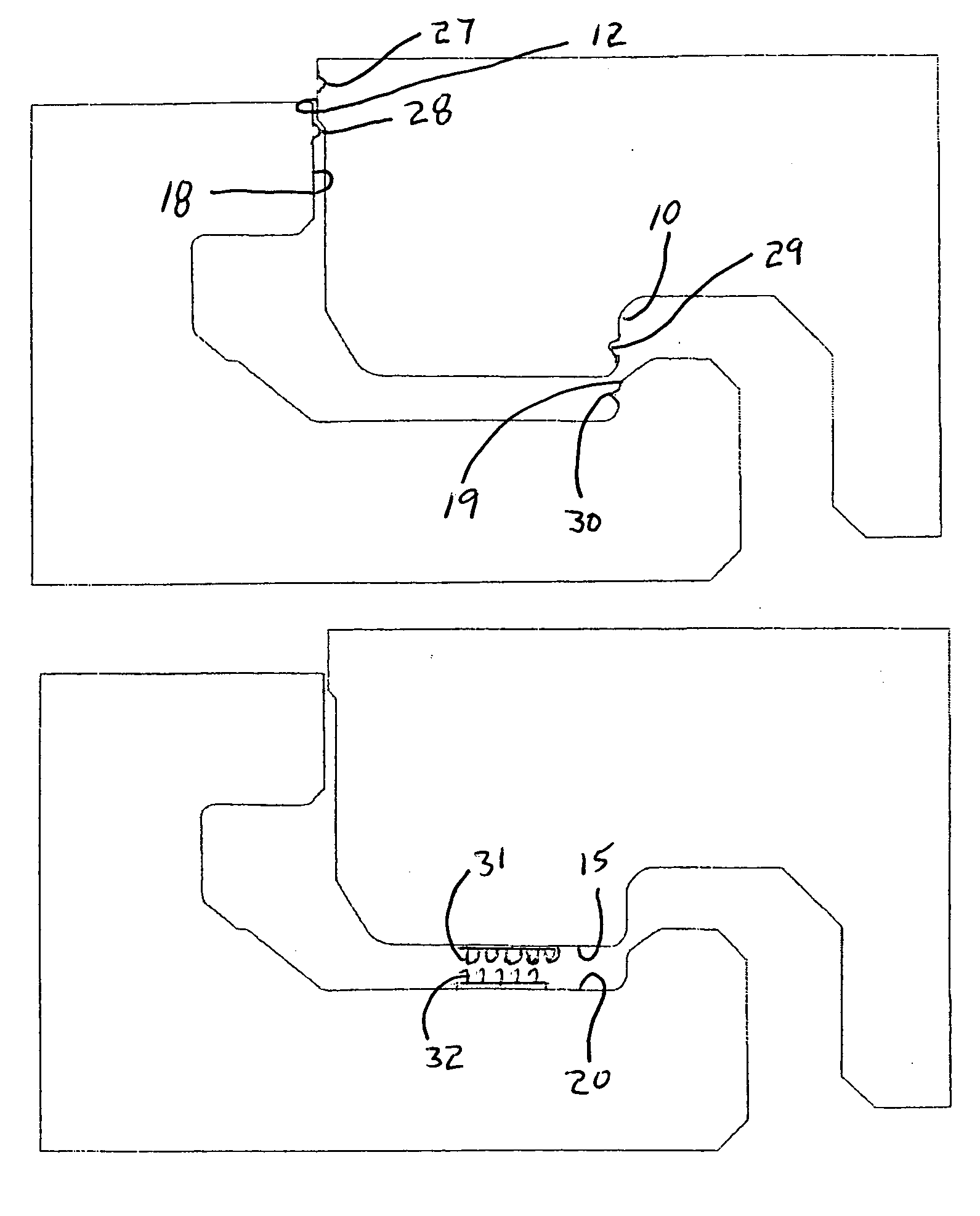
[0038] The upper lip locking projection 6 is formed on the upper lip 8 of the short side of panel 4 between the distal end 9 and the upper lip proximal groove 10. The upper lip proximal groove 10 is formed between the upper lip locking projection 6 and the body of the panel 4 adjacent the lower surface 11. The upper lip 8 includes an upper lip distal contact surface 12 and an upper lip proximal contact surface 14. The upper li...


PUM


Abstract

Lock and fold floor covering panels can be installed by angling a long locking edge into a previously installed row of panels and dropping or locking the projection of the tongue of the short side into the depression of the lower lip forming the groove in the short side. By incorporating a force increasing means in the fold joint, the width of the panels that can be installed with a lock and fold system can be increased beyond the conventionally accepted 3.5 inches. The fold joint is designed to permit it to be engaged, disengaged and reengaged without damaging the fold joint.

Description

FIELD OF THE INVENTION [0001] The present invention relates generally to the field of flooring including wood laminate flooring, such as high density fiberboard (HDF) laminate flooring and medium density fiberboard (MDF) laminate flooring, solid wood flooring and engineered wood flooring, which includes a plurality of wood layers. More particularly, the present invention relates flooring having locking edge profiles BACKGROUND OF THE INVENTION [0002] Floor covering panels, including wood laminate flooring, solid wood flooring and engineered wood flooring are well known in the prior art. To increase the ease of installation by removing the need for glues or adhesives, these floor coverings have been made with locking edges having a tongue with a projection and a groove with a corresponding depression in the core of the floor covering panel that together form coupling parts or means, which prevents substantial movement perpendicular to the major surfaces of the laminate flooring and p...

Claims


Application Information

Patent Timeline
Patent Type & Authority Applications(United States)
IPC IPC(8): E04B2/00
CPCE04F15/02E04F2201/0138E04F2201/035E04F2201/07E04F2201/08
Inventor GOODWIN, MILTON W.ORR, MARK L.
Owner ARMSTRONG WORLD INDUSTRIES
Why Eureka
Try Eureka