Motor vehicle coolant circuit comprising a pump and a retarder

a technology of retarder and coolant circuit, which is applied in the direction of vehicle heating/cooling devices, engine cooling apparatus, brake systems, etc., can solve the problems of increasing the total flow resistance or flow resistance of the coolant in the cooling circuit, increasing the fuel consumption of the motor vehicle, and not being able to employ any conventionally dimensioned coolant pump

Inactive Publication Date: 2007-06-14
VOITH TURBO GMBH & CO KG
View PDF9 Cites 12 Cited by
  • Summary
  • Abstract
  • Description
  • Claims
  • Application Information

AI Technical Summary

Benefits of technology

[0009] The invention is based on the problem of creating a coolant circuit that has a coolant pump and a retarder and that is improved over the prior art. In particular, it should be possible to use a coolant pump that does not requ

Problems solved by technology

The provision of such retarders in the cooling circuit can result in an increase in the total flow resistance or the resistance of flow of the coolant in the cooling circuit.
Accordingly, it is not possible to employ any conventi

Method used


Image

  • Motor vehicle coolant circuit comprising a pump and a retarder
  • Motor vehicle coolant circuit comprising a pump and a retarder
  • Motor vehicle coolant circuit comprising a pump and a retarder

Examples


Embodiment Construction

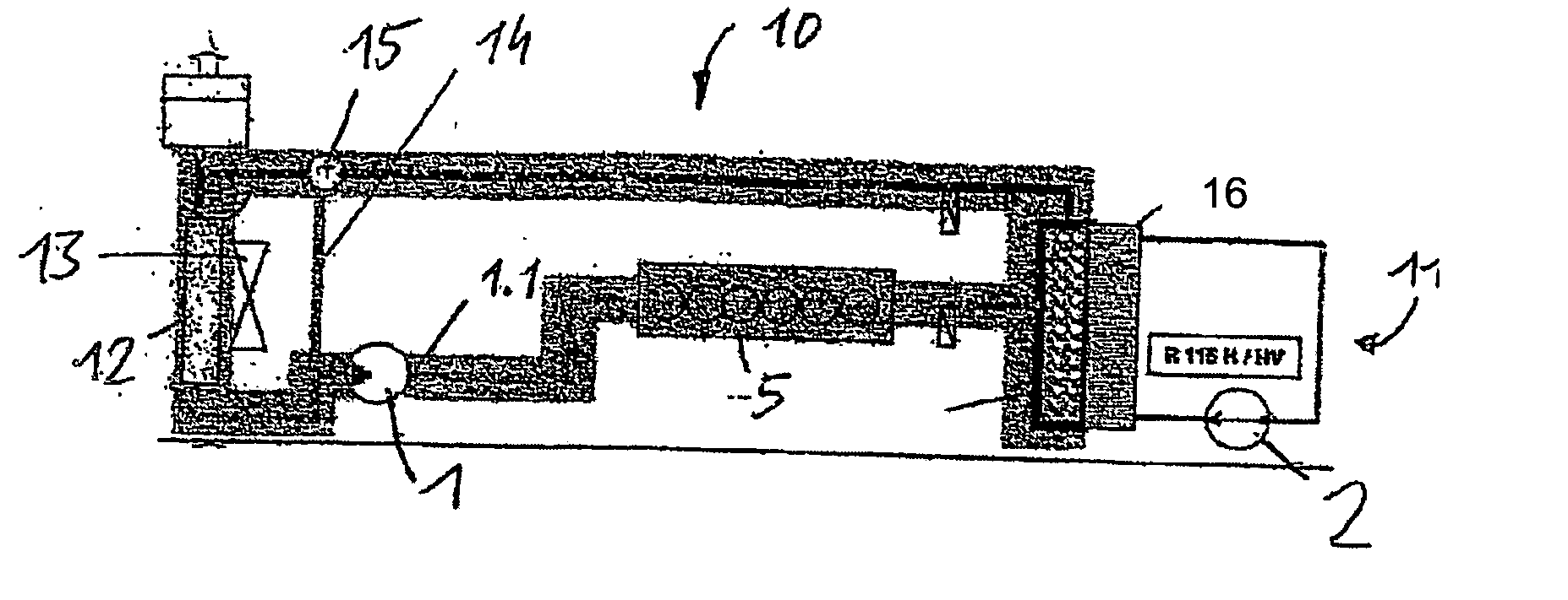
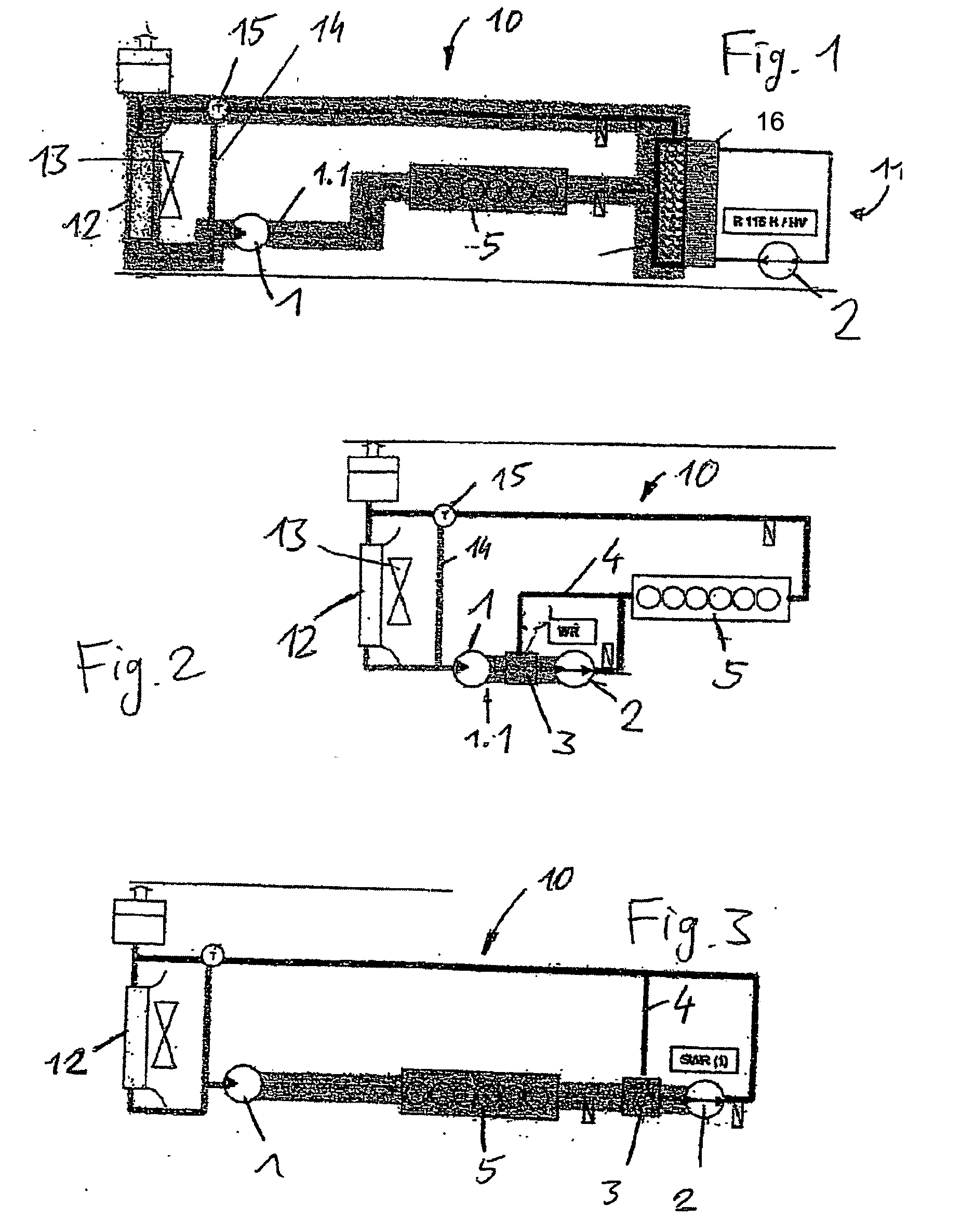
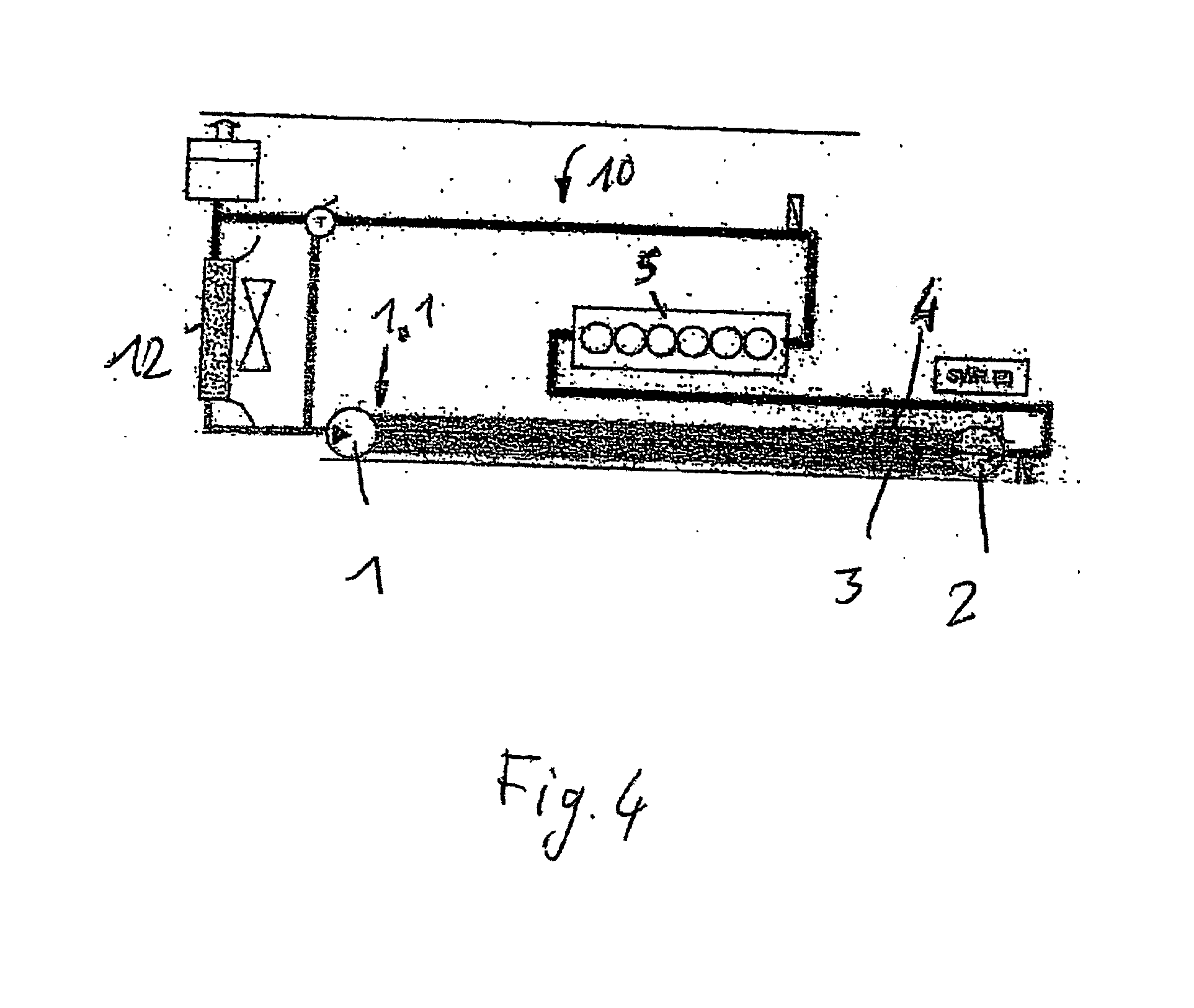
[0024] Evident in FIG. 1 are a coolant circuit 10 and a retarder working medium circuit 11. In accordance with the prior art, the two circuits are constructed separately. The coolant in the coolant circuit 10 is circulated by means of the coolant pump 1 and the working medium in the retarder circuit 11 is circulated by means of the retarder 2. The two circuits are connected to each other by means of an oil-water heat exchanger 12 in such a way that the heat generated in the retarder 2 is transferred to the coolant circuit 10. Conventionally, the heat is dissipated from the coolant circuit 10 by means of a water-air radiator 16 together with a fan wheel 13. Insofar as there exists no necessity of dissipating the heat from the coolant circuit 10 on account of the coolant temperature, the coolant is conveyed past the radiator by means of the bypass 14. A thermostat 15 is provided for an appropriate regulation.

[0025] The flow of cooling medium, particularly the flow of cooling water th...


PUM


Abstract

A coolant circuit of a motor vehicle, including the following features: a coolant, especially water or a water mixture; a coolant pump having a coolant outlet; a retarder provided with a central ring, the working medium thereof being the coolant; a reversing valve in the flow direction upstream of the retarder and a bypass section for bypassing the retarder, such that the retarder can be connected to and disconnected from the coolant circuit. According to the invention, the coolant pump is arranged in the flow direction upstream of the retarder in such a way that it pumps coolant into the retarder when the retarder is connected, and pumps coolant past the retarder via the bypass section when the retarder is disconnected.

Description

RELATED APPLICATIONS [0001] This application claims priority in PCT International Application No. PCT / EP2004 / 007546, filed Jul. 9, 2004, and German Application No. DE 103 32 907.2-16 filed Jul. 19, 2003, the contents of which are incorporated herein by reference.BACKGROUND OF THE INVENTION [0002] 1. Field of the Invention [0003] The invention relates to a coolant circuit of a motor vehicle, which comprises both a coolant pump and a retarder, the working medium of the retarder being the coolant. [0004] 2. Description of the Related Art [0005] A hydraulic oil has been conventionally used as the working medium of a retarder in the driveline of a motor vehicle. On account of the heat produced in the braking mode, the hydraulic oil had to be cooled. Provided for this purpose was, as a rule, an oil-water heat exchanger as interface between the cooling circuit and the working medium circuit of the retarder, by means of which the requisite quantity of heat was dissipated from the retarder c...

Claims


Application Information

Patent Timeline
IPC IPC(8): F01P7/14F01P1/06F02N17/06B60T10/02F01P3/20F02N19/10F16D57/04
CPCB60T10/02F01P3/20F01P2007/146F16D57/005F16D57/04B60T1/087
Inventor VOGELSANG, KLAUS
Owner VOITH TURBO GMBH & CO KG
Why Eureka
Try Eureka