MEMS flow sensor

a flow sensor and microelectromechanical technology, applied in the field of flow sensors, can solve the problems of low end resolution and dynamic range capabilities of flow meters that are typically required

Inactive Publication Date: 2007-06-14
GENERAL ELECTRIC CO
View PDF11 Cites 23 Cited by
  • Summary
  • Abstract
  • Description
  • Claims
  • Application Information

AI Technical Summary

Problems solved by technology

Also, such flow meters lack the low end resolution and dynamic range capabilities that are typically required for respiratory flow measurements needed in biomedical applications.

Method used


Image

  • MEMS flow sensor
  • MEMS flow sensor
  • MEMS flow sensor

Examples


Embodiment Construction

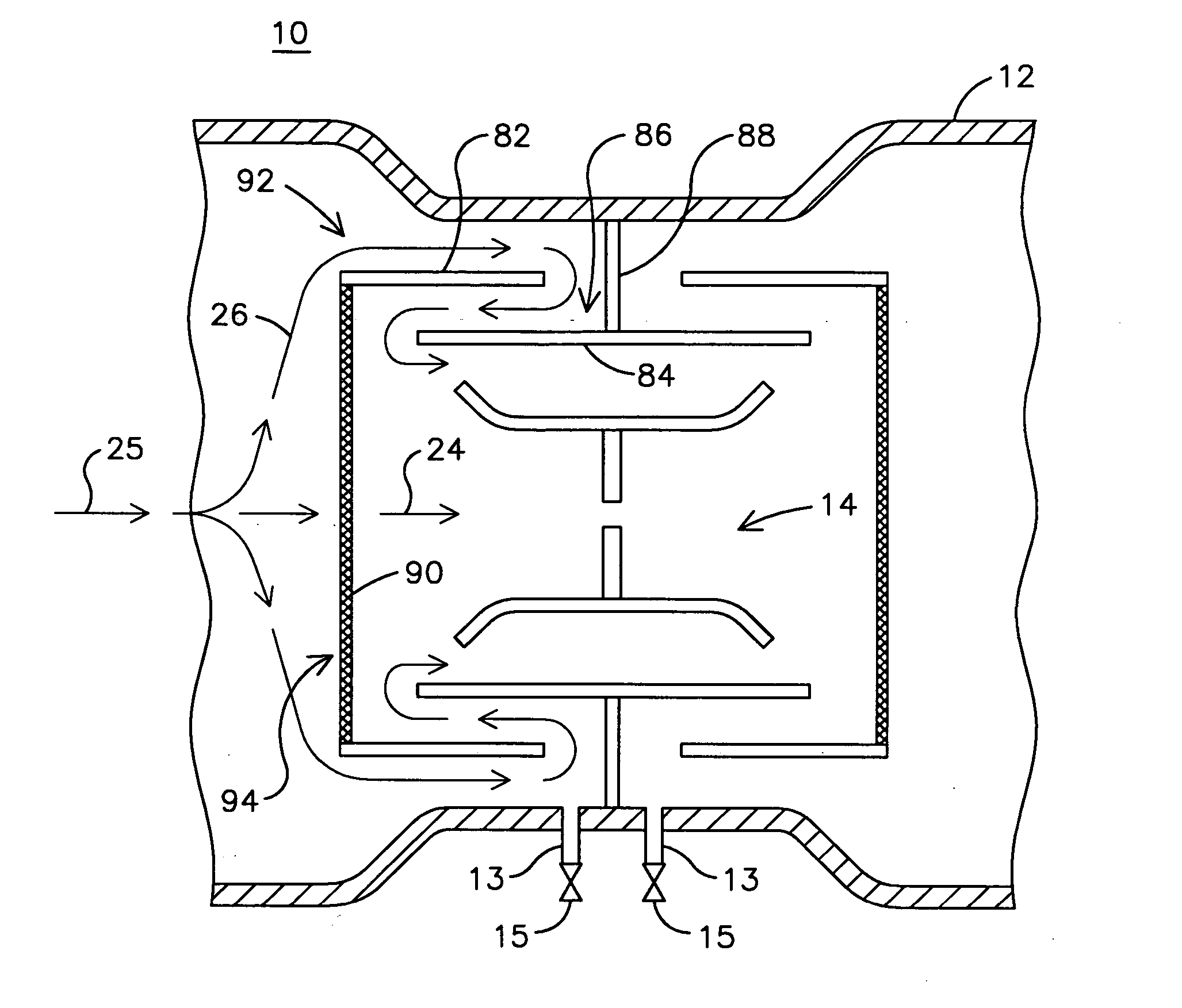
[0010] The inventors have developed an innovative MEMS based micro-fluidic flow sensor that overcomes the disadvantages of conventional flow sensors such as described above. Advantageously, the innovative MEMS based micro-fluidic flow sensor has the ability to directly provide an electronic output which can be processed more easily as compared to a differential pressure output provided by conventional flow sensors. In addition, significant cost savings may be realized compared to conventional flow sensors.

[0011] Flow sensors having variable orifices (that is, orifices that change in size responsive to a fluid flow parameter) have been proposed to achieve a desired dynamic range and low pressure resolution needed for measuring respiratory flows. However, such flow sensors typically transect an entire bore of a respirator tube conducting an airflow to be measured and may be susceptible to contamination, for example, by exhaled mucus and / or water vapor. Water vapor may result in water...


PUM


Abstract

A micro-electro-mechanical, micro-fluidic flow sensor (14) includes a flow separating element (15) for separating a first portion (24) of a fluid flow (25) from a second portion (26) of the fluid flow. The flow sensor also includes a flow obstructing member (17) disposed in the first portion of the flow for at least partially obstructing the first portion of the flow. The flow obstructing member deflects in response to the first portion of the flow so that a degree of partial obstruction of the first portion of the flow by the flow obstructing member varies in response to the first portion of the fluid flow.

Description

FIELD OF THE INVENTION [0001] The present invention is generally related to fluid flow sensors, and, more particularly, to a micro-electro-mechanical (MEMS) based micro-fluidic flow sensor for a biomedical machine performing a flow measurement. BACKGROUND OF THE INVENTION [0002] Biomedical flow meters, such as flow meters for respirator, ventilators, anesthesia-machines, and / or incubators, etc., need to have sufficient dynamic range and high resolution at low flow for required performance, for instance, to accurately determine exhalation and inhalation airflow of a patient using the machine. Conventional differential pressure based flow meters may use an orifice, venturi, or pitot tube to establish a pressure differential in a fluid flow which may be sensed and interpreted as a measure of the fluid flow. Typically, such flow meters require maintenance to keep them clean of mucus and water vapor that may be exhaled by a patient. Also, such flow meters lack the low end resolution and ...

Claims


Application Information

Patent Timeline
Patent Type & Authority Applications(United States)
IPC IPC(8): F17D1/16
CPCA61B5/0876A61M16/08A61M2016/0036G01F1/28G01F1/363G01F1/383G01F1/40G01F5/005G01F15/00G01F15/125A61M2016/0027Y10T137/0396
Inventor THAKRE, PARAGPHUKAN, ATANUCHANDRA, NIKHILARADHYA, SRIHARSHA
Owner GENERAL ELECTRIC CO
Why Eureka
Try Eureka