
Pneumatic tire

a pneumatic tire and allweather technology, applied in the direction of non-skid devices, vehicle components, transportation and packaging, etc., can solve the problems of uneven wear, insufficient traction performance and steering stability, and inability to achieve satisfactory steering stability, etc., to achieve excellent drainage properties, perform well on snow, and uneven wear is hardly caused

Inactive Publication Date: 2007-06-14
BRIDGESTONE CORP
View PDF3 Cites 15 Cited by
  • Summary
  • Abstract
  • Description
  • Claims
  • Application Information

AI Technical Summary

Benefits of technology

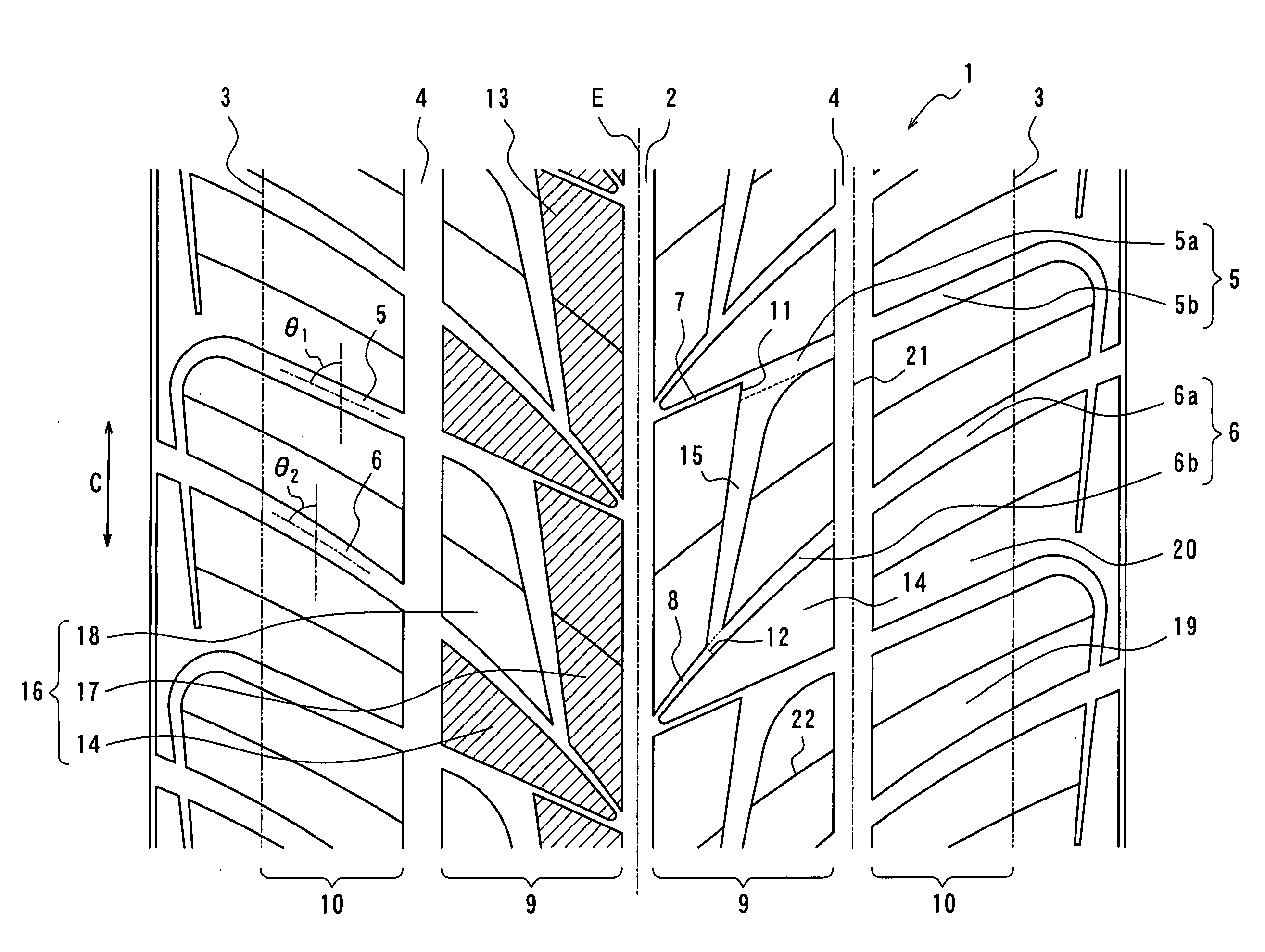
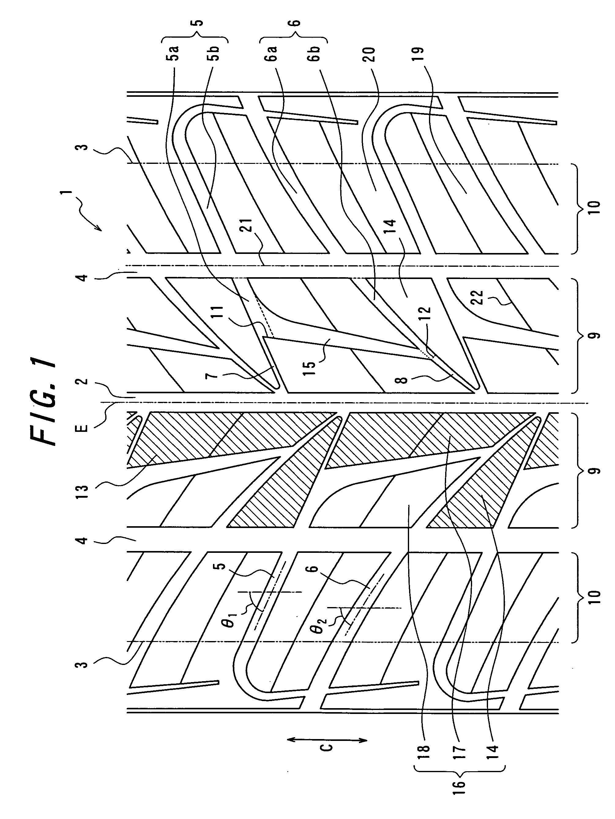
[0011] It is, therefore, an object of the invention to provide a pneumatic tire, particularly an all-weather type pneumatic tire in which excellent drainage property and performances on snow are developed without deteriorating the other performances and the uneven wearing is hardly caused by appropriating first and second gently slant grooves located between the central main groove and the side main groove and arranging given fine grooves between terminal ends of these gently slant grooves and the central main groove.
[0022] According to the invention, there can be provided a pneumatic tire, particularly an all-weather type pneumatic tire in which excellent drainage property and performances on snow are developed without deteriorating the other performances and the uneven wearing is hardly caused by appropriating first and second gently slant grooves located between the central main groove and the side main groove and arranging given fine grooves between terminal ends of these gently slant grooves and the central main groove.

Problems solved by technology

However, there is a problem that as the negative ratio is made large, the rigidity of land portion lowers and hence the satisfactory steering stability is not obtained.
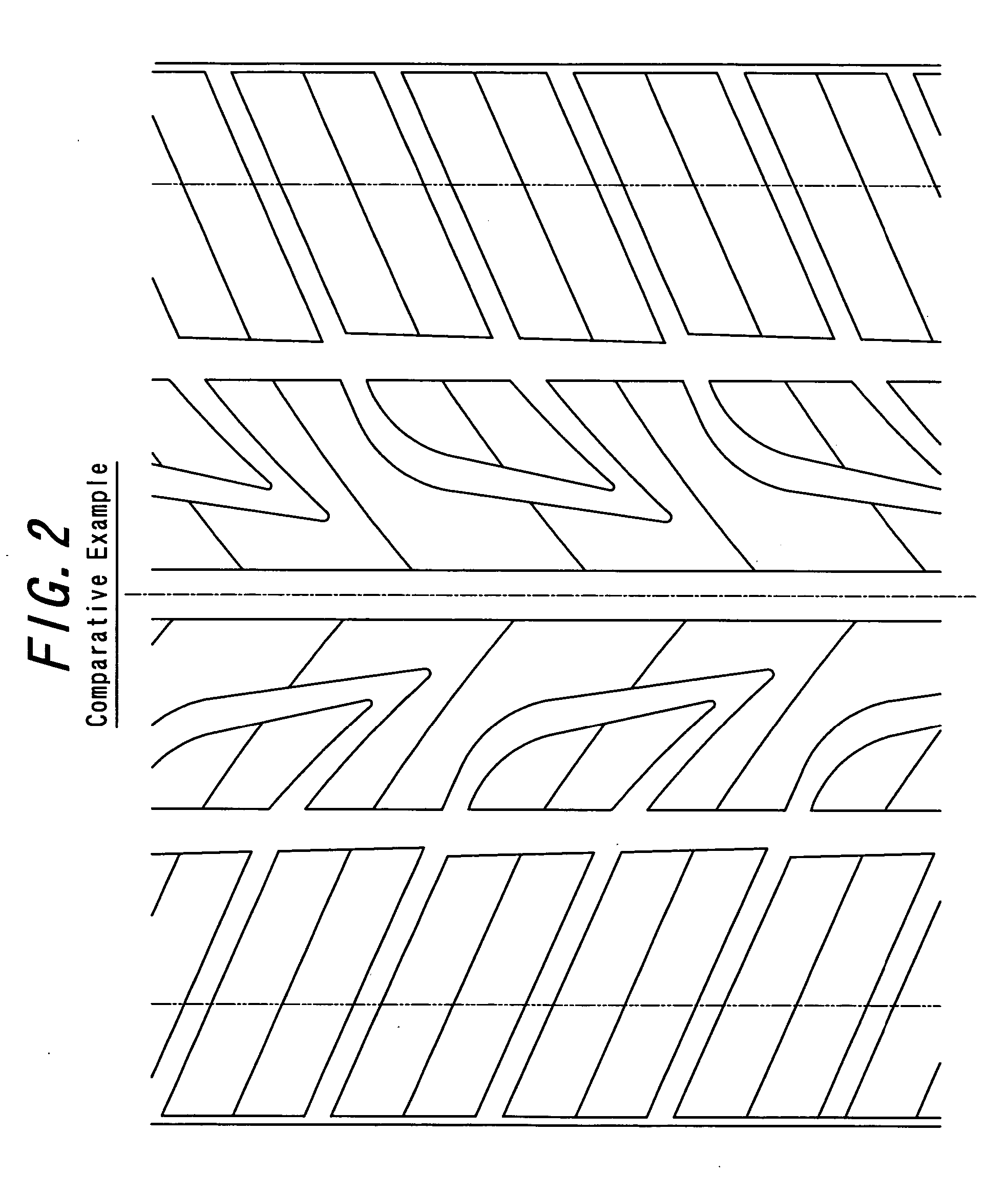
In a block pattern wherein the steeply slant groove is opened to the main groove located at the central zone, however, a corner part of the block defined between the central main groove and the steeply slant groove becomes acute-angled and the rigidity as a whole of land portions located at the central zone is generally insufficient, and hence the traction performance and steering stability can not be sufficiently ensured and also the uneven wearing is easily caused.
In case of the tread pattern wherein the steeply slant groove (portion) is terminated in the land portion located short of the central main groove as described in the above patent document, however, all of water taken in the central main groove from the central zone in the contacting with ground is drained only toward the forward-backward direction of the tire, so that the drainage property can not be said to be sufficient, and there is still left a room for improving the drainage property.

Method used


Image

  • Pneumatic tire
  • Pneumatic tire
  • Pneumatic tire

Examples


example 1

[0047] There is prepared a pneumatic tire according to the invention having a tread pattern shown in FIG. 1, in which a tire size is 205 / 55R16 and a tread width is 180 mm, and a groove width, a groove depth and a groove angle with respect to a central main groove 2, a side main groove 4, a first gently slant groove 5, a second gently slant groove 6, a first fine groove 7, a second fine groove 8 and a steeply slant groove 15 are collectively shown in Table 1. Each of plural side blocks constituting a side land portion has a ground contacting area within a range of ±30% of an average value, and among a plurality of central blocks constituting a central land portion, a ground contacting area of a central block having a maximum ground contacting area is 1.1-2 times of a ground contacting area of a central block having a minimum ground contacting area. Also, a shift length in the circumferential direction between an extension of a groove width center line in the groove portion located at...


PUM


Abstract

In a pneumatic tire having excellent drainage property and performances on snow, a central main groove 2 and a side main groove 4 and first and second gently slant grooves 5, 6 are arranged in a tread portion 1, and the first and second gently slant grooves 5, 6 are terminated in a central land portion 9 between the central main groove 2 and the side main groove 4, and first and second fine grooves 7, 8 are further arranged so as to extend from terminal ends 11, 12 of the first and second gently slant grooves 5, 6 toward the central main groove 2 and open thereto, respectively.

Description

BACKGROUND OF THE INVENTION [0001] 1. Field of the Invention [0002] This invention relates to a so-called all-weather type pneumatic tire considering performances in a winter season. [0003] 2. Description of the Related Art [0004] The all-weather tire is an all-purpose tire capable of running not only on dry and wet road surfaces but also on ice and snow road surfaces. Such a tire is common to have a block pattern formed by arranging on a tread portion straight or zigzag main grooves extending in a circumferential direction of the tire and a plurality of slant grooves crossing these main grooves. [0005] As a means for improving the drainage property, it is useful to take a method of increasing a ratio of groove area or so-called negative ratio by widening a groove width of the each groove. However, there is a problem that as the negative ratio is made large, the rigidity of land portion lowers and hence the satisfactory steering stability is not obtained. [0006] As to the drainage p...

Claims


Application Information

Patent Timeline
IPC IPC(8): B60C11/00
CPCB60C11/0302B60C11/12B60C11/13B60C11/033B60C2011/0374Y10S152/03
Inventor FUJITA, SHUNGO
Owner BRIDGESTONE CORP
Learn More