Rotating electrical machine or alternator and method of manufacturing rotor core used in the same

a technology of rotating electrical machines and alternators, which is applied in the direction of magnetic circuit rotating parts, forging/pressing/hammering apparatus, and shape/form/construction of magnetic circuits, etc., can solve the problems of deteriorating efficiency and increasing magnetic resistance, and achieve the effect of ensuring sufficient magnetic performan

Inactive Publication Date: 2007-06-14
HITACHI LTD
View PDF18 Cites 5 Cited by
  • Summary
  • Abstract
  • Description
  • Claims
  • Application Information

AI Technical Summary

Benefits of technology

[0011] According to the present invention, claws of the rotor core are hard to open in the radial direction even under the action of a centrifugal force

Problems solved by technology

This leads to another problem that magnetic resistance is increased in a magnetic path e

Method used


Image

  • Rotating electrical machine or alternator and method of manufacturing rotor core used in the same
  • Rotating electrical machine or alternator and method of manufacturing rotor core used in the same
  • Rotating electrical machine or alternator and method of manufacturing rotor core used in the same

Examples


Embodiment Construction

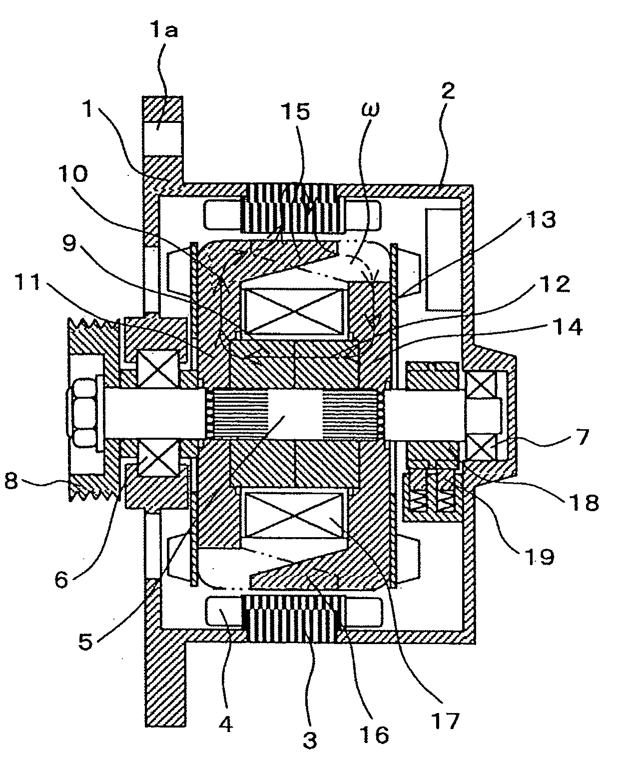
[0032] One example of a vehicular alternator will be described below as a typical example of a rotating electrical machine according to one embodiment of the present invention. FIG. 1 is a longitudinal sectional view of the vehicular alternator.

[0033] A stator core 3 is held between a front housing 1 and a rear housing 2. The front housing 1, the rear housing 2, and the stator core 3 are fixed together by tightening screws and nuts (not shown) to apply a strong force in the direction in which the front housing 1 and the rear housing 2 grip the stator core 3 between them. The front housing 1 includes a flange 1a which is used to fix the alternator to a bracket provided on an engine block (not shown). The stator core 3 has a plurality of teeth formed along an entire inner periphery facing the rotor side, and stator coils 4 are wound over the teeth. Three-phase AC voltages are induced in the stator coils 4 with the rotation of magnetized rotor cores 11 and 14 (described later).

[0034]...


PUM

PropertyMeasurementUnit
Flow rateaaaaaaaaaa
Diameteraaaaaaaaaa
Adhesion strengthaaaaaaaaaa

Abstract

A rotor core which has relatively high rigidity, can ensure sufficient magnetic performance, and can be produced at a cheaper cost with a relatively small-scale facility. A claw-equipped core and a yoke are manufactured separately. After fitting the yoke to a fitting portion formed in the claw-equipped core, a part of the claw-equipped core in the vicinity of the fitting portion is axially pressed to plastically flow into an annular groove formed in the yoke, thereby integrally joining the claw-equipped core and the yoke to each other. Thus, a large-scaled manufacturing facility is not required, and claws of the claw-equipped core are hard to open in the radial direction even under the action of a centrifugal force during high-speed rotation. A stator core and the claws of the claw-equipped core can be positioned closer to each other, and deterioration of magnetic performance can be avoided.

Description

BACKGROUND OF THE INVENTION [0001] 1. Field of the Invention [0002] The present invention relates to a rotating electrical machine or an alternator and a method of manufacturing a rotor core used in the rotating electrical machine or the alternator. [0003] 2. Description of the Related Art [0004] In a known alternator, plate-like rotor cores are disposed at opposite ends of a cylindrical yoke which is disposed in the inner peripheral side, and a plurality of claws are axially projected from outer peripheries of the rotor cores in alternately interdigitated relation. A shaft is inserted within the yoke. Further, because of the necessity of arranging a field coil between inner peripheries of the claws and an outer periphery of the yoke, the yoke is divided into a plurality of pieces and the divided yoke pieces are fixed to each other after arranging the field coil in place. [0005] Patent Document 1 (JP-B-61-000979) discloses a rotor core structure in which claw-equipped cores and a yo...

Claims


Application Information

Patent Timeline
IPC IPC(8): H02K1/22H02K15/02
CPCH02K1/243H02K5/08Y10T29/49012B21K1/28H02K15/022B21K25/00
Inventor HARADA, KOJI
Owner HITACHI LTD
Why Eureka
Try Eureka