Control unit for electric power steering apparatus

a technology of control unit and electric power steering, which is applied in the direction of electronic commutators, dynamo-electric converter control, instruments, etc., can solve the problems of complex abnormality judging processing, long processing time, and inability to refer to a table of criteria

Inactive Publication Date: 2007-06-14
NSK LTD +1
View PDF0 Cites 9 Cited by
  • Summary
  • Abstract
  • Description
  • Claims
  • Application Information

AI Technical Summary

Benefits of technology

[0010] The present invention relates to a control unit for an electric power steering apparatus for applying a steering assist force by a motor to a steering system of a vehicle. To achiever the above object of the invention, the control unit comprises: a plurality of position detecting sensors for detecting a rotation position of the motor and outputting it as binary outputs; a state function calculating means which calculates a output value of a state function for every predetermined time by inputting outputs of the plurality of position detecting sensors to the state function; and a judging means to be input the output values of the state function which respectively continued through the predetermined time, so as to judge a rotating direction of the motor and abnormality of rotating direction detection of the motor at one time.
[0011] Furthermore, to achieve the above object of the invention, the state function is a function the output value of which is in a one-to-one relationship with the rotation position of the motor without redundancy or the control unit comprises relative steering angle calculating means for converting each of the clockwise rotation, the counterclockwise rotation, and the stop obtained from the rotating direction into a numerical value and integrating the numerical value every predetermined time to calculate a steering wheel relative steering angle or a column relative steering angle. Moreover, to achieve the above object of the invention, the control unit comprises steering velocity calculating means for calculating a steering wheel steering velocity or a column steering velocity by using the steering wheel relative steering angle or the column relative steering angle and the predetermined time.

Problems solved by technology

Moreover, processing takes much time in referring to a table of criteria of judgment for judging whether the sensors are abnormal or normal, because a plurality of conditional statements are used.
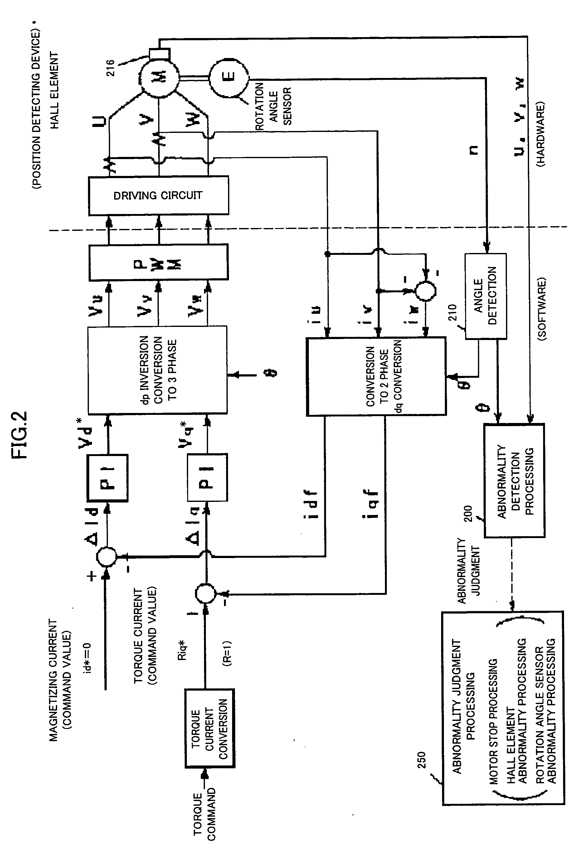
Moreover, because both the rotation angle sensor and the Hall element 216 are used, an abnormality judging processing becomes complicated.

Method used


Image

  • Control unit for electric power steering apparatus
  • Control unit for electric power steering apparatus
  • Control unit for electric power steering apparatus

Examples


Embodiment Construction

[0023] A basic theory of the present invention will be described and then concrete embodiments will be described.

[0024] A theory in detecting a position of a rotor while disposing three position detecting sensors HS1, HS2, and HS3 for detecting the position of the rotor of a motor will be described. As the position detecting sensor, a sensor such as a Hall sensor for outputting a binary signal is most suitable and is widely available as an inexpensive part. If the three Hall sensors are disposed at regular intervals of 120°, relationships among the binary outputs of them are shown in FIG. 3. The output of the position detecting sensor HS1 changes from “0” to “1” or from “0” to “1” at every 180° of the rotation angle. The output of the position detecting sensor HS2 changes from “0” to “1” or from “0” to “1” at every 180° of the rotation angle with a 120° phase shift from the output of the position detecting sensor HS1. The output of the position detecting sensor HS3 changes from “0”...


PUM


Abstract

In the present invention, only an abnormality of detection of a rotating direction of a motor is detected and therefore, with simple processing and by using a table for judging the abnormality of the detection of a rotating direction of a motor and the rotating direction of the motor, the abnormality of the detection of a rotating direction and the rotating direction of the motor are judged at one time.

Description

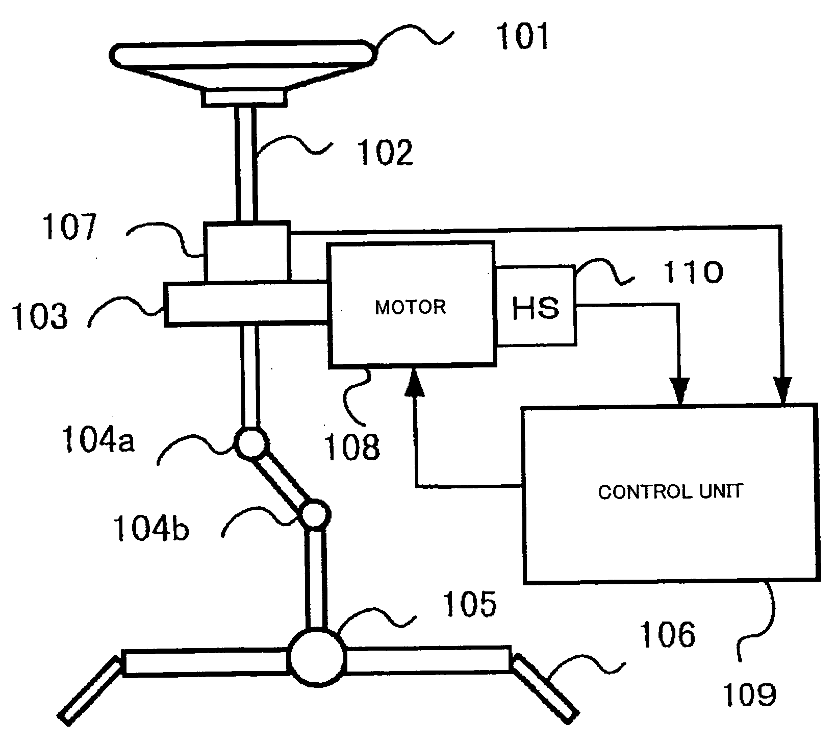
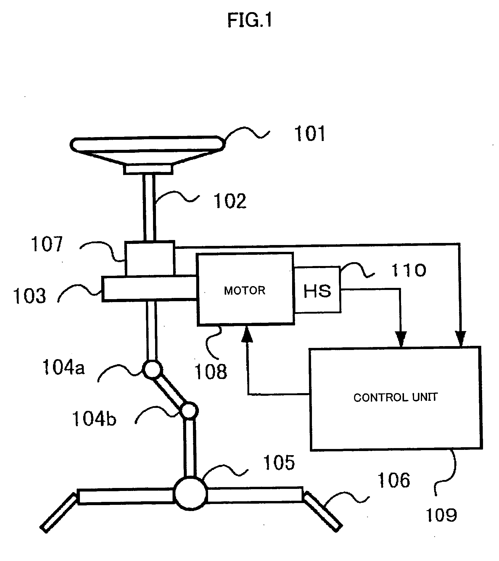
TECHNICAL FIELD [0001] The present invention relates to a control unit for an electric power steering apparatus for applying a steering assist force by a motor to a steering system of an automobile or a vehicle and especially to a control unit for an electric power steering apparatus for carrying out detection of a rotating direction of a motor and the like with low-cost sensors. BACKGROUND ART [0002] An electric power steering apparatus for applying a steering assist force to a steering mechanism of an automobile by a rotating force of a motor transmits a driving force of the motor by a transmitting mechanism such as a gear or a belt through a reduction gear to apply the steering assist force to a steering shaft or a rack shaft. An example of a structure of such an electric power steering apparatus is shown in FIG. 1 and will be described. [0003] A shaft 102 of a steering wheel 101 is coupled to tie rods 106 of steered wheels through a reduction gear 103, universal joints 104a and ...

Claims


Application Information

Patent Timeline
Patent Type & Authority Applications(United States)
IPC IPC(8): H02P7/00G01B21/22B62D5/04B62D6/00B62D113/00G01D5/244H02P6/06H02P6/08H02P6/15H02P6/16H02P6/22H02P6/30H02P21/06
CPCB62D5/049H02P21/06
Inventor ARAI, KENJIAOKI, YUHO
Owner NSK LTD
Why Eureka
Try Eureka