RF shielding method, MRI apparatus, and transmtiting/receiving surface coil

a shielding method and surface coil technology, applied in the field of rf shielding methods, can solve the problems that the use of high-performance filters also becomes unnecessary, and achieve the effect of reducing the cost of isolation

Inactive Publication Date: 2007-06-14
GE MEDICAL SYST GLOBAL TECH CO LLC
View PDF31 Cites 19 Cited by
  • Summary
  • Abstract
  • Description
  • Claims
  • Application Information

AI Technical Summary

Benefits of technology

[0007] Therefore, it is an object of the present invention to provide an RF shielding method, an MRI apparatus, and a transmitting/r...

Problems solved by technology

Moreover, it becomes unnecessary to use a bias power supply of a large current or lar...

Method used


Image

  • RF shielding method, MRI apparatus, and transmtiting/receiving surface coil
  • RF shielding method, MRI apparatus, and transmtiting/receiving surface coil
  • RF shielding method, MRI apparatus, and transmtiting/receiving surface coil

Examples


first embodiment

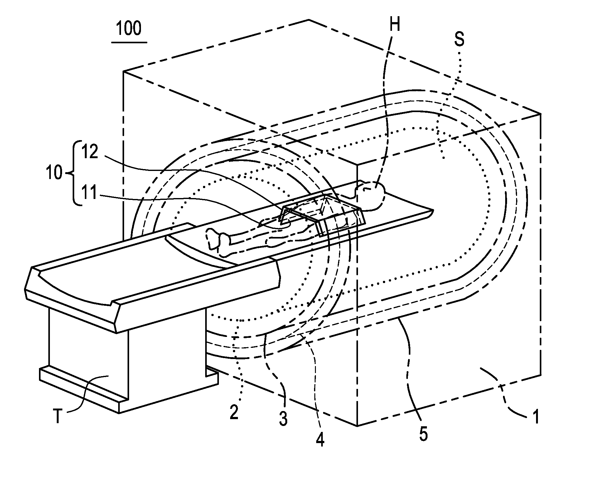
[0036]FIG. 1 is a perspective view showing an MRI apparatus 100 and a transmitting / receiving surface coil 10 according to a first embodiment of the present invention.

[0037] In the MRI apparatus 100, a body coil 2, an RF shield 3 for the body coil, and a gradient magnetic field coil 4, are disposed in the interior of a magnet assembly 1 concentrically and in this order from the inner periphery side. A main magnetic field generating magnet 5 is disposed outside the gradient magnetic field coil 4. Further, a bore (a cylindrical space) S for insertion therein of a subject H placed on a cradle of a table unit T is formed in the magnet assembly 1.

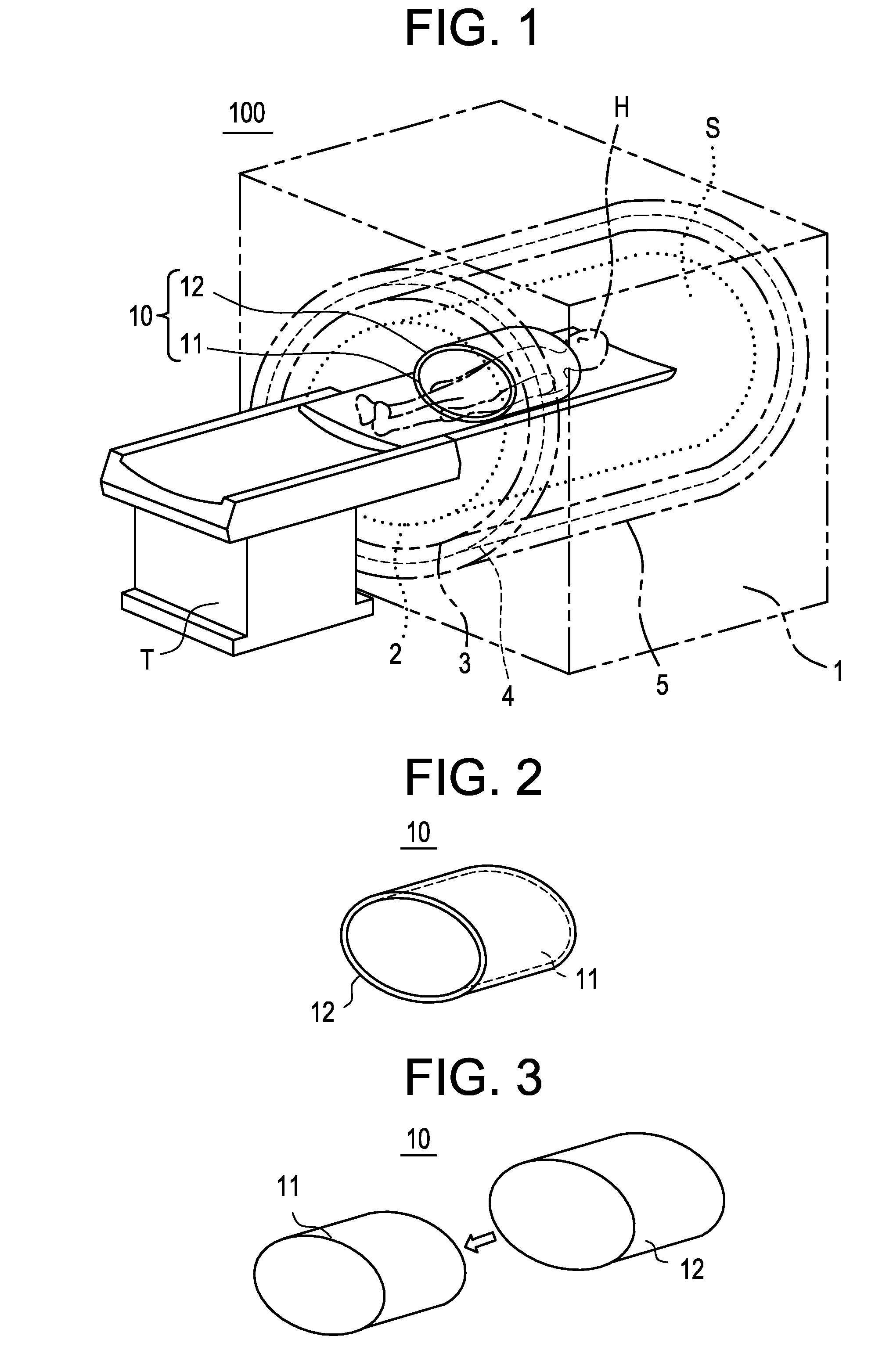
[0038] The transmitting / receiving surface coil 10, which is cylindrical, is mounted to the subject H.

[0039] The transmitting / receiving surface coil 10 is made up of a cylindrical surface coil body 11 and a cylindrical RF shield 12 for the surface coil which shield 12 surrounds the outer periphery of the surface coil body 11.

[0040] In the tran...

second embodiment

[0042] As shown in FIG. 3, a surface coil body 11 and an RF shield 12 for a surface coil in a transmitting / receiving surface coil 10 may be made separate from each other.

[0043] According to the transmitting / receiving surface coil 10 of this second embodiment, by applying the RF shield 12 for the surface coil over the outer periphery of the surface coil body 11, the reception by the body coil 2 of RF pulses transmitted from the surface coil body 11 can be suppressed. On the other hand, by removing the RF shield 12 for the surface coil from the outer periphery of the surface coil body 11, the body coil 2 can be used as a transmitting coil.

third embodiment

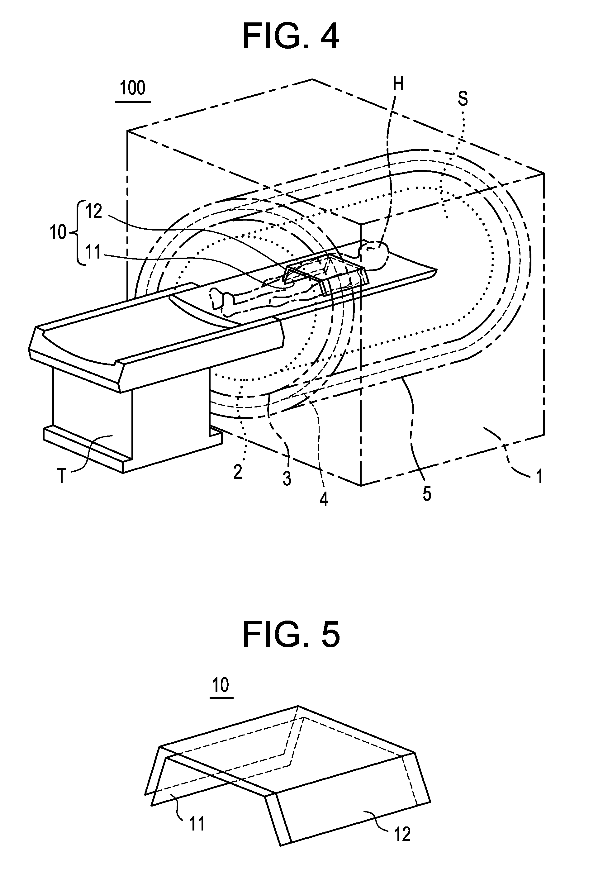
[0044] As shown in FIG. 4, there may be used a plate-like transmitting / receiving surface coil 10.

[0045] This transmitting / receiving surface coil 10 is made up of a plate-like surface coil body 11 and a plate-like RF shield 12 for the surface coil which shield is disposed on the side opposite to the subject with respect to the surface coil body 11.

[0046] As shown in FIG. 5, the surface coil body 11 and the RF shield 12 for the surface coil in the transmitting / receiving surface coil10 are integral with each other.


PUM


Abstract

In order to reduce the cost for isolation between a surface coil and a body coil installed on a magnet assembly side, an RF shield for a surface coil is disposed between a body coil installed on a magnet assembly side of an MRI apparatus and a surface coil body not installed on the magnet assembly side. The reception by the body coil of RF pulses transmitted from the surface coil body is suppressed by the RF shield for the surface coil. Since an induced voltage in the body coil drops to a great extent, a switch provided on the body coil side no longer requires a component resistant to high voltage and high current. Thus, the apparatus can be simplified and the cost can be reduced. As a result, the reliability of the apparatus is improved.

Description

BACKGROUND OF THE INVENTION [0001] The present invention relates to an RF shielding method, an MRI (Magnetic Resonance Imaging) apparatus, and a transmitting / receiving surface coil. More particularly, the present invention is concerned with an RF shielding method, an MRI apparatus, and a transmitting / receiving surface coil, which can reduce the cost for isolation of a body coil installed on a magnet assembly side, from a surface coil. [0002] Heretofore, there has been known a technique wherein an RF shield is provided between a body coil installed on a magnet assembly side and a gradient magnetic field coil (see, for example, Patent Literatures 1 and 2). [0003] [Patent Literature 1] Japanese Unexamined Patent Publication No. 2000-11619 [0004] [Patent Literature 2] Japanese Unexamined Patent Publication No. 2004-248928 [0005] Heretofore, isolation of a gradient magnetic field coil against RF pulses transmitted from a body coil installed on a magnet assembly side has been performed th...

Claims


Application Information

Patent Timeline
IPC IPC(8): G01V3/00
CPCG01R33/341G01R33/3657G01R33/422A61B5/055G01R33/48
Inventor OGINO, TETSUO
Owner GE MEDICAL SYST GLOBAL TECH CO LLC
Why Eureka
Try Eureka