Circuit and method for modifying a region of an encoded image

a technology of encoded images and circuits, applied in the field of image processing techniques, can solve the problems and achieve the effect of reducing the processing circuit, cost and complexity

Inactive Publication Date: 2007-06-14
MEYER BROS TECH GROUP
View PDF29 Cites 25 Cited by
  • Summary
  • Abstract
  • Description
  • Claims
  • Application Information

AI Technical Summary

Benefits of technology

[0032] Such a circuit allows one to modify a region of an image by decoding and re-encoding only that region instead of the entire image. For example, if one wishes to overlay an EPG on a bottom portion of a video frame, then the circuit can decode only the EPG and the bottom portion of the frame, overlay the decoded EPG on the bottom frame portion, and re-encode the overlaid bottom frame portion. Therefore, this technique often reduces the processing time, and thus the cost and complexity of the processing circuit, as compared to a circuit that decodes and re-en codes the entire frame during an image overlay process.

Problems solved by technology

Therefore, this technique often reduces the processing time, and thus the cost and complexity of the processing circuit, as compared to a circuit that decodes and re-en codes the entire frame during an image overlay process.

Method used


Image

  • Circuit and method for modifying a region of an encoded image
  • Circuit and method for modifying a region of an encoded image
  • Circuit and method for modifying a region of an encoded image

Examples


Embodiment Construction

Formatting Encoded Video Images Into Respective Multiple Independent Regions

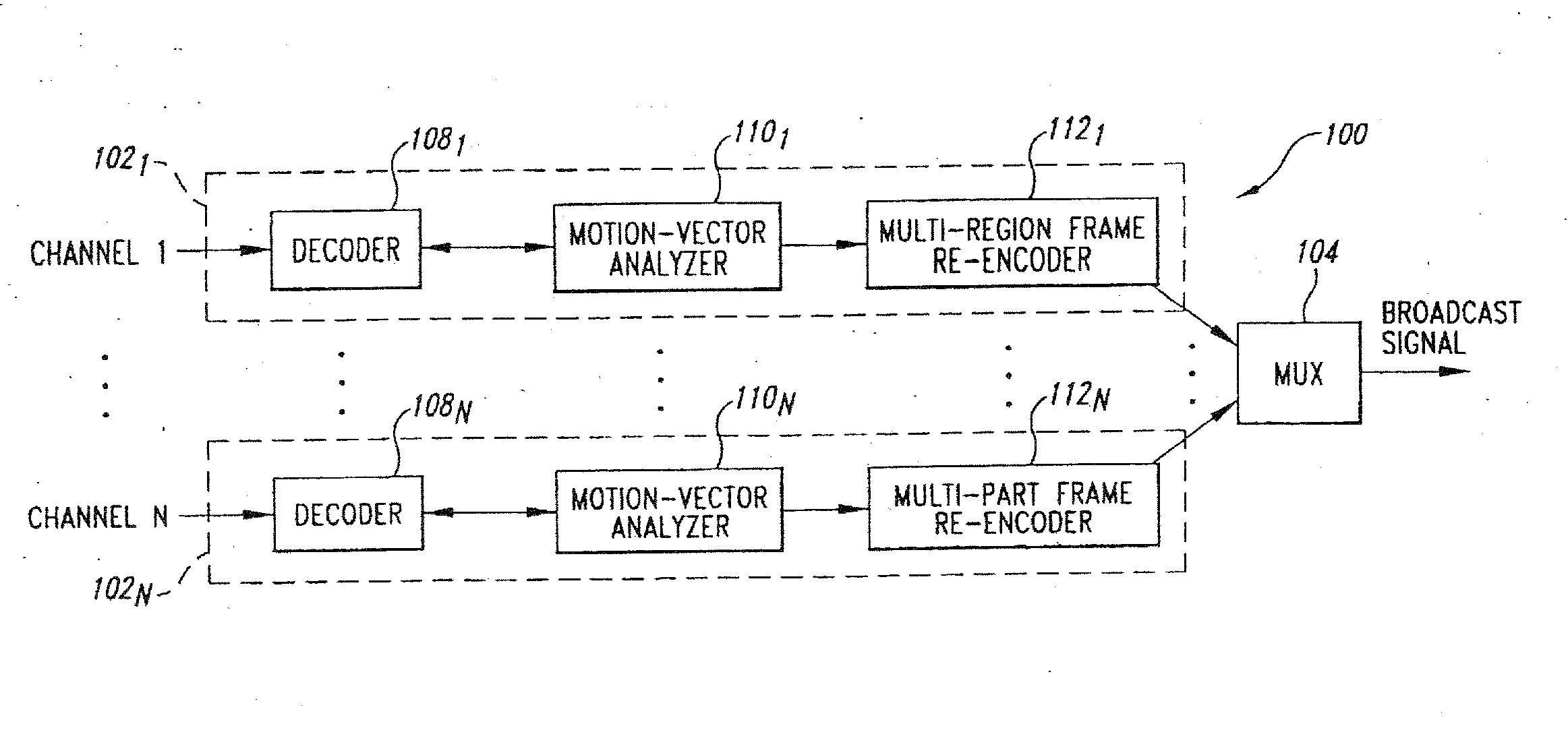
[0045]FIG. 7 is a block diagram of a video-frame formatter 100 according to an embodiment of the invention. The formatter 100 includes video processing circuits 1021-102N for respectively formatting encoded video-channel signals 1-N received from respective broadcaster networks (e.g., FOX, CNN). Specifically, the processing circuits 102 format the frames of each respective channel signal such that the frames each have multiple independent regions. The processing circuits 102 then provide the respective processed channel signals 1-N to a multiplexer 104, which combines all of the processed channel signals into an encoded multiplexed broadcast video signal. Although described as formatting video frames, the formatter 100 can be designed to modify video fields or still images.

[0046] For example purposes, the structure and operation of the video processing circuit 1021 is discussed in detail, it being underst...


PUM


Abstract

A video processing circuit includes a processor that receives an encoded image having first and second regions, decodes the first region of the image, modifies the decoded first region, and re-encodes the modified first region. Such a circuit allows one to modify a region of an image by decoding and re-encoding only that region instead of the entire image. For example, if one wishes to overlay an EPG on a bottom portion of a video frame, then the circuit can decode only the EPG and the bottom portion of the frame, overlay the decoded EPG on the bottom frame portion, and re-encode the overlaid bottom frame portion. Therefore, this technique often reduces the processing time, and thus the cost and complexity of the processing circuit, as compared to a circuit that decodes and re-encode the entire frame during an image overlay process.

Description

[0001] This application is a divisional of pending U.S. patent application Ser. No. 09 / 390,241, filed on Sep. 3, 1999, the disclosure of which is incorporated herein in its entirety by reference.TECHNICAL FIELD [0002] The invention relates generally to image-processing techniques, and more particularly to a circuit and method for modifying a region of a encoded image. For example, the invention allows one to blend an electronic program guide (EPG) with a region of an encoded video frame without decoding the entire frame. BACKGROUND OF THE INVENTION [0003]FIG. 1 is a video image 6, which is a video frame that includes a first region 7 and a second region 8. Although described as a video frame for example purposes, the image 6 may also be a video field. Furthermore, although shown as two rectangles in a top-bottom arrangement, the number, shape, and respective locations of these regions is arbitrary. [0004] Typically, one views a sequence of video frames 6 in their respective entireti...

Claims


Application Information

Patent Timeline
Patent Type & Authority Applications(United States)
IPC IPC(8): G09G5/00H04N5/445H04N5/262H04N7/025H04N7/03H04N7/035H04N7/26
CPCH04N19/48H04N19/90H04N19/40H04N19/27H04N19/89H03M13/00
Inventor EASWAR, VENKAT V.O'DONNELL, JOHN S.NATARAJAN, RAMACHANDRANGOVE, ROBERT J.
Owner MEYER BROS TECH GROUP
Why Eureka
Try Eureka