Security monitoring system with image comparison of monitored location

a security monitoring and image comparison technology, applied in the field of videophone systems, can solve the problems of wasting time and expense in traveling to and from different facilities, unable to meet the needs of users,

Inactive Publication Date: 2007-06-14
TELEBUYER
View PDF103 Cites 47 Cited by
  • Summary
  • Abstract
  • Description
  • Claims
  • Application Information

AI Technical Summary

Problems solved by technology

While previous monitoring systems have been effective, particularly in conjunction with a single facility, there have been attendant limitations.
Unfortunately, more time and expense is incurred in traveling to and from different facilities than is desirable.
However, obstacles remain, particularly in traditional areas of cumbersome communication.
At present, no one industry standard and format has been adopted for video conferencing systems.
Thus, the systems available on the market are not always compatible.
To consider an example of cumbersome communication in the merchandising industry, wholesale vendors or sellers of goods typically spend many hours attempting to schedule appointments with various buyers for different organizations, travelling to and from the buyers' facilities, and waiting for meetings, which may sometimes last only a short duration.
Unfortunately, considerably more time and expense is incurred, in travelling to and from different facilities, than is desirable.
Moreover, in the event a specific seller wishes to broadcast a special offering of a particular item to plural buyers, for example, to dispose of an inventory of distressed items, the seller must undertake considerable effort, such as place an advertisement or otherwise initiate contact with buyers.
An advertisement is likely to be viewed only by random buyers, thus, not always proving to be a reliable method of soliciting offers from all possible buyers.
Moreover, initiating individual contact with a series of buyers, until eventually securing a final sale, constitutes an arduous task.

Method used


Image

  • Security monitoring system with image comparison of monitored location
  • Security monitoring system with image comparison of monitored location
  • Security monitoring system with image comparison of monitored location

Examples


Embodiment Construction

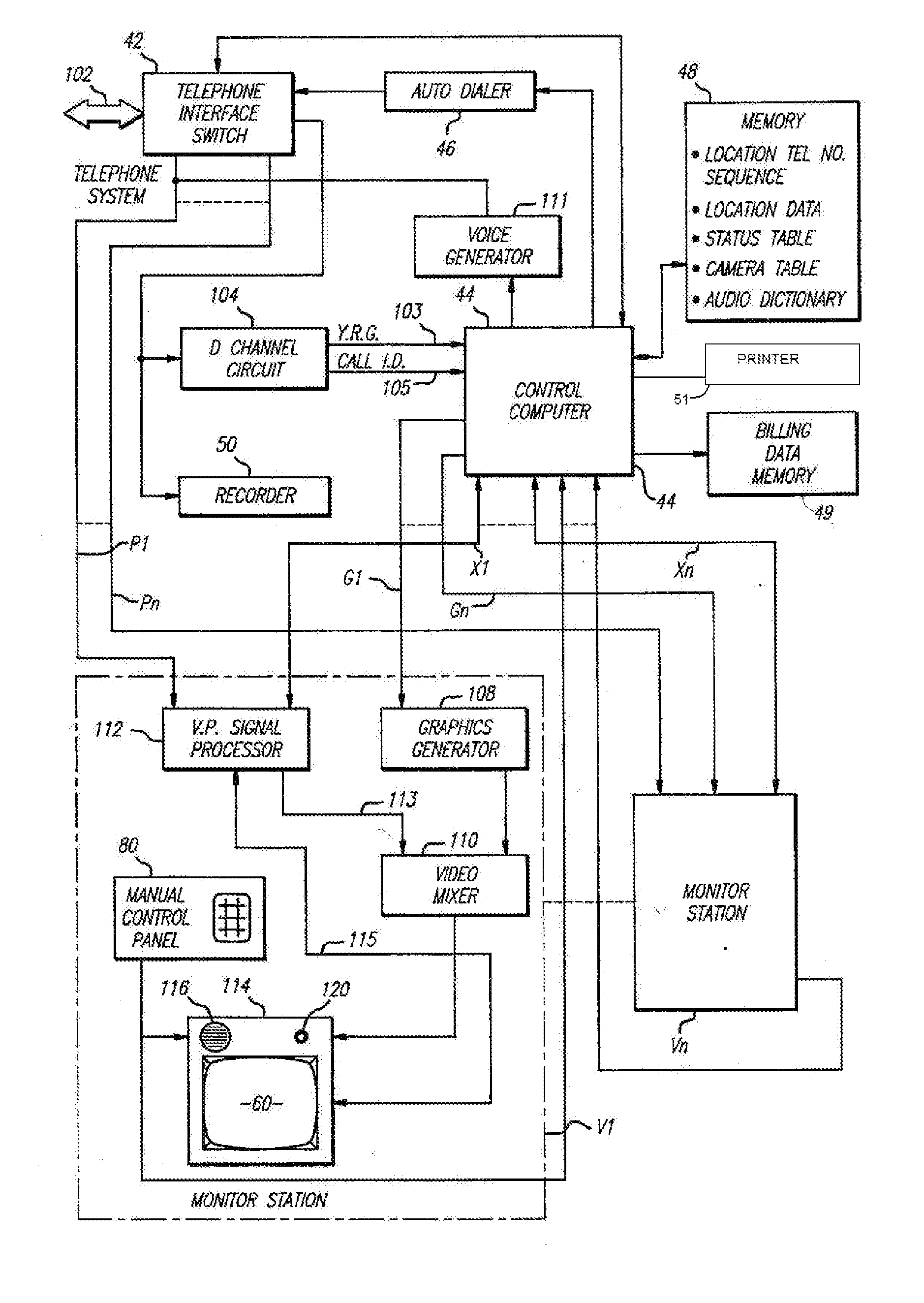
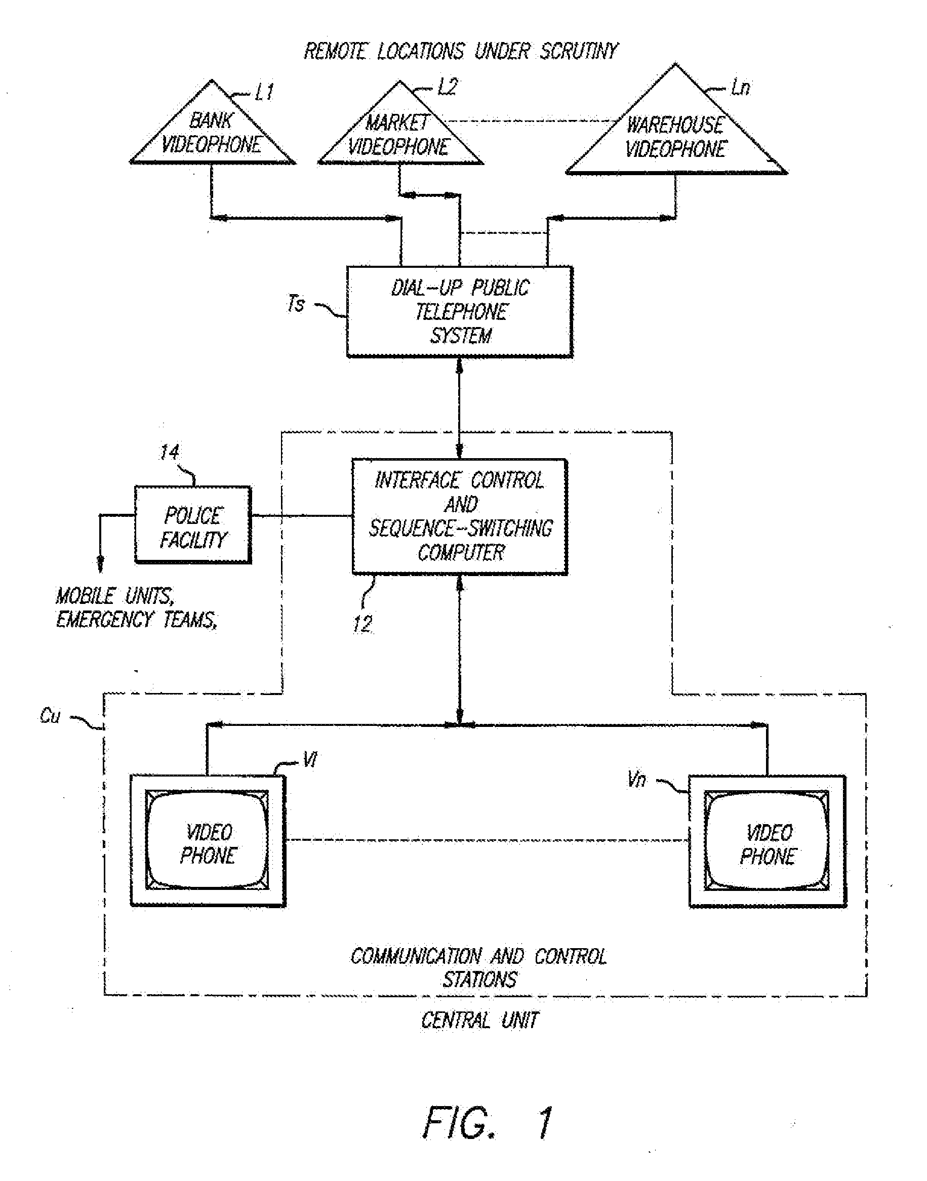
[0043] Generally, the system of the present invention involves monitoring and communicating with a plurality of remote widely distributed locations from a central unit utilizing dial-up telephone facilities, in today's computer environment with voice quality lines under computer control. Specifically, the dynamic graphics of telephonic video along with audio capabilities are combined with the interactive capability of computers to attain an effective security system.

[0044] Communication between the central system and the remote locations may be accomplished in a variety of ways, as for example, by electronic-mail (transmission of messages across a network between two desktop PCs), electronic bulletin boards, on-line computer services (such as Prodigy™ or CompuServe™), facsimile, voice-mail or the like.

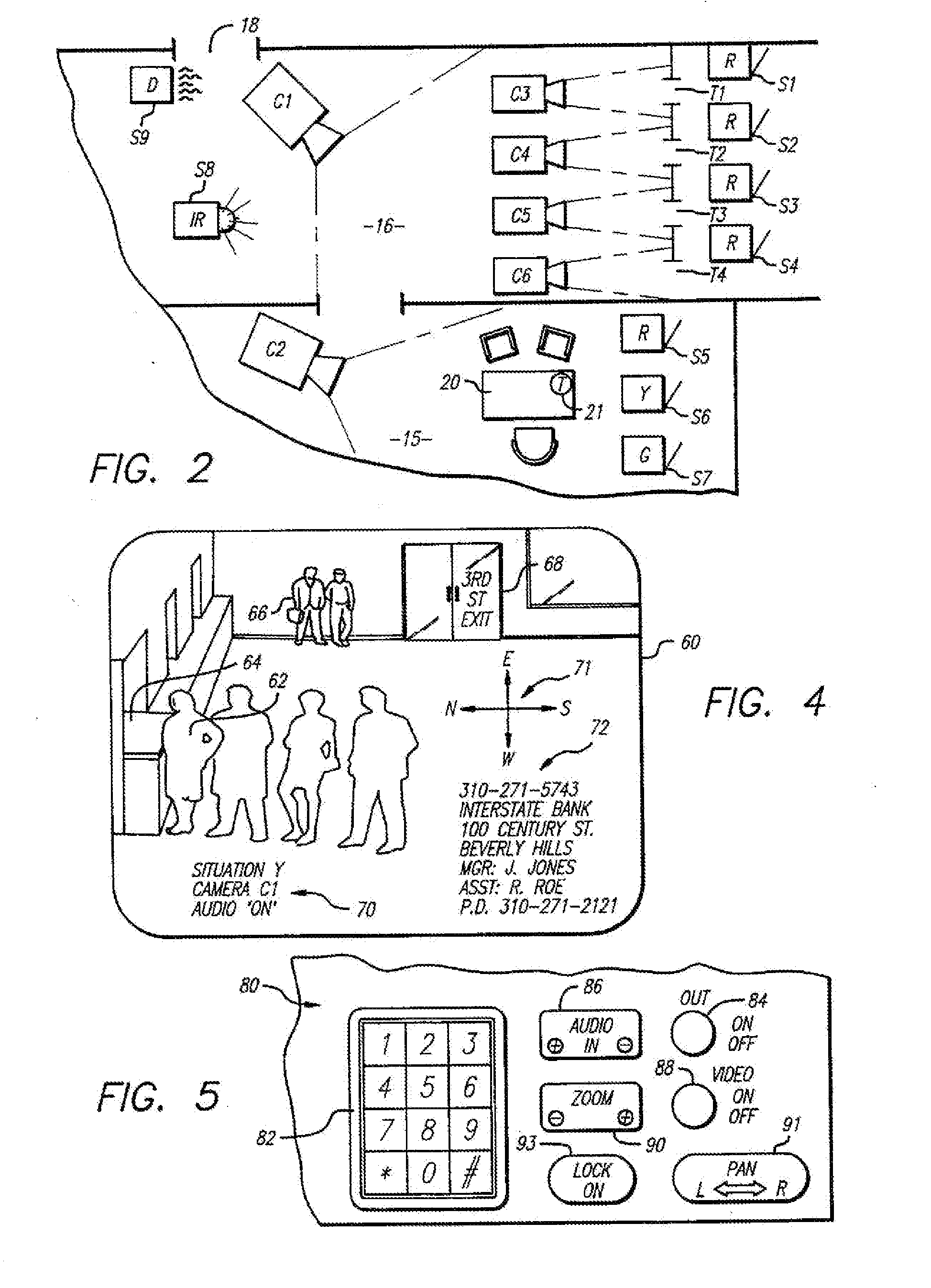
[0045] The system of the present invention contemplates use for applications ranging from, prevention of armed robberies and burglaries to quality control and regulation, as of food ...


PUM


Abstract

A security monitoring system has a monitoring location and a remote location with at least one monitoring device. A first image from one of the monitoring devices is recorded, and then compared with a second image from the same monitoring device. When the amount of change between the first and second images exceeds a predetermined threshold, then a scrutiny situation signal is generated. The video recorder may be located at either the monitoring location or the remote location. In some cases, the first and second video images are sent from the remote location to the monitoring location via a temporary communication channel that has at least one portion that is provided by an online computer service. In some cases, the first and second video images are sent from the remote location to the monitoring location via a temporary communication channel that has at least one wireless portion.

Description

CROSS-REFERENCE TO RELATED APPLICATIONS [0001] This application is a continuation of co-pending application Ser. No. 09 / 371,212, entitled “METHOD FOR BUYER-SELLER ON-LINE COMMERCE” and filed on Aug. 10, 1999, now pending, which is a continuation of application Ser. No. 08 / 189,405, entitled “COMMERCIAL PRODUCT ROUTING SYSTEM WITH VIDEO VENDING CAPABILITY” and filed on Jan. 27, 1994, now U.S. Pat. No. 6,323,894, which is a continuation-in-part of application Ser. No. 08 / 154,313, entitled “SCHEDULING AND PROCESSING SYSTEM FOR TELEPHONE VIDEO COMMUNICATION” and filed on Nov. 17, 1993, now U.S. Pat. No. 5,495,284, which is a continuation-in-part application of application Ser. No. 08 / 067,783, entitled “VIDEOPHONE SYSTEM FOR SCRUTINY MONITORING WITH COMPUTER CONTROL” and filed on May 25, 1993, now abandoned, which is a continuation-in-part application of application Ser. No. 08 / 031,235, entitled “VIDEOPHONE SYSTEM FOR SCRUTINY MONITORING WITH COMPUTER CONTROL” and filed on Mar. 12, 1993, ...

Claims


Application Information

Patent Timeline
Patent Type & Authority Applications(United States)
IPC IPC(8): H04N7/14H04N7/18G06Q30/00H04M3/42H04M3/432H04M3/493H04M3/51H04M3/56H04M7/00H04M11/00H04N7/15H04N21/2187H04N21/4223H04N21/433H04Q9/00
CPCG06Q20/208H04N21/4334G06Q30/0601G06Q30/0613G06Q30/08G08B13/19645G08B13/19658G08B13/19689H04M3/2281H04M3/42H04M3/432H04M3/493H04M3/51H04M3/5125H04M3/5158H04M3/564H04M3/565H04M3/567H04M7/006H04N5/76H04N7/142H04N7/147H04N7/152H04N21/2187H04N21/4223G06Q30/02
Inventor KATZ, RONALD A.
Owner TELEBUYER
Why Eureka
Try Eureka