Filtered noise reduction in digital images

a digital image and noise reduction technology, applied in image enhancement, image analysis, color signal processing circuits, etc., can solve the problems of reducing the luminance content of the image by a large amount, and reducing the noise in the digital image, so as to reduce the noise, reduce the noise, and reduce the noise. effect of digital imag

Inactive Publication Date: 2007-06-14
EASTMAN KODAK CO
View PDF1 Cites 25 Cited by
  • Summary
  • Abstract
  • Description
  • Claims
  • Application Information

AI Technical Summary

Benefits of technology

[0004] The present invention provides a method of reducing noise in a digital image produced by a digital imaging device, includes producing a luminance and at least one chrominance channel from a full-color digital image with each channel having a plurality of pixels and each such pixel has a value; producing an edge value from corresponding neighboring pixels in neighborhoods in the at least one chrominance channel; modifying the pixel value in the chrominance channel with an infinite impulse response filter responsive to the edge value of the corresponding pixel neighborhood to provide a modified chrominance channel; and producing a full-color digital image from the luminance channel and the modified chrominance channel, with reduced noise.
[0005] The invention uses IIR filters applied directly to the chrominance portions of a single digital still image to achieve strong noise reduction without degrading the luminance content of the image. A feature of the invention is that IIR filter can be adaptive. Additionally, IIR filters are particularly suitable to effect a direct spatial frequency decomposition of the luminance information of the image so that nonlinear noise reduction methods are used to more effectively reduce noise without degrading genuine scene details.
[0006] It is a feature of the present invention that a strong level of noise reduction can be achieved without degrading the genuine image details.
[0007] It is another feature of the present invention that computational requirements are reduced through the use of in-place computations, small pixel neighborhoods, and single-branch adaptive strategies.

Problems solved by technology

A significant problem with approaches based on noise reduction of the luminance information in the image is that strong noise reduction to address high noise levels generally requires significant degradation to the genuine image details.

Method used


Image

  • Filtered noise reduction in digital images
  • Filtered noise reduction in digital images
  • Filtered noise reduction in digital images

Examples


embodiment 216

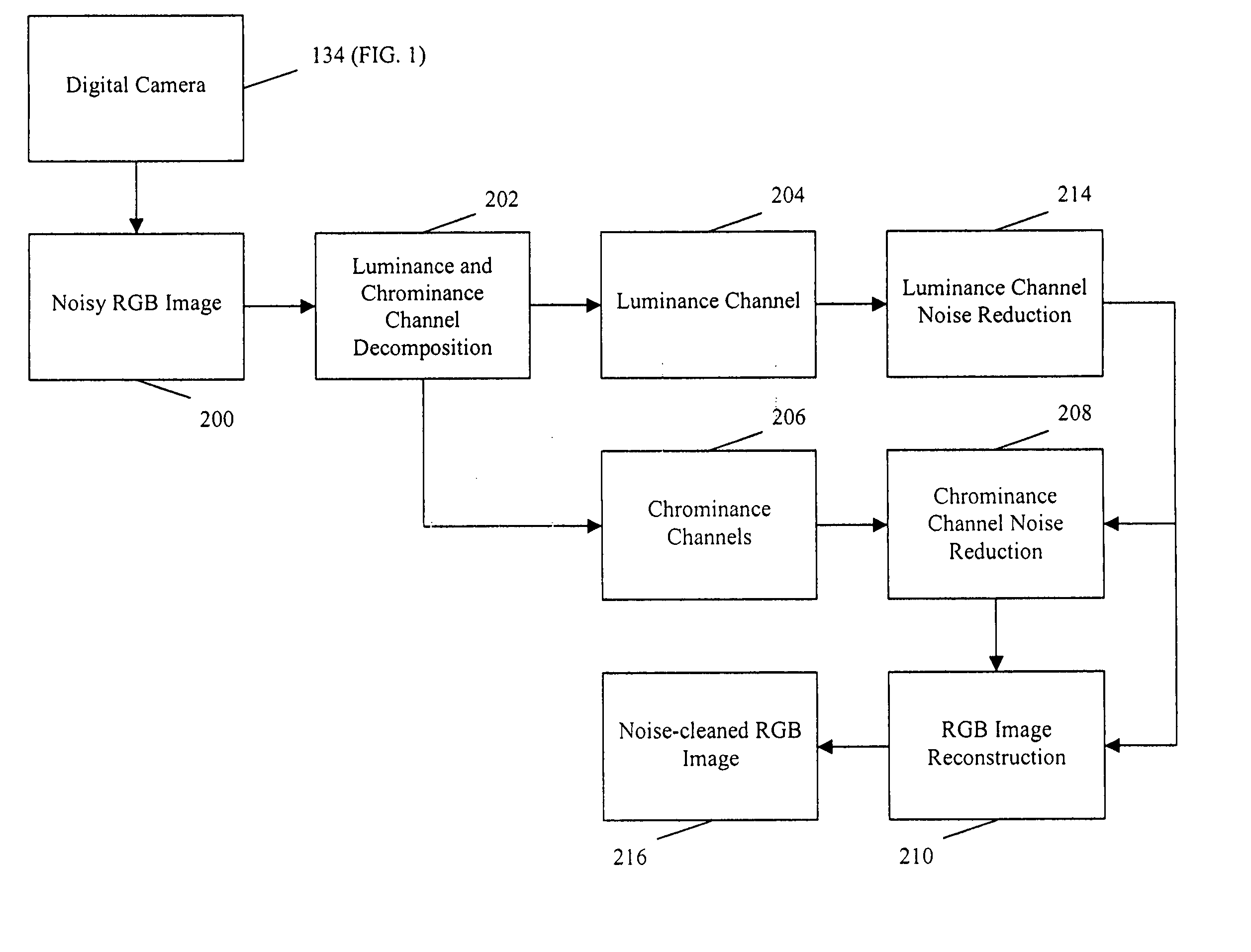
[0030]FIG. 6 is a high level diagram of an alternate embodiment. The digital camera 134 is responsible for creating an original red-green-blue (RGB) image that presumably contains noise (noisy RGB image) 200. This image is first decomposed into luminance and chrominance channels 202 as previously described. The luminance values together compose the luminance channel 204 and the chrominance values together compose the chrominance channels 206. The luminance channel is passed to the luminance channel noise reduction block 214 in which the noise in the luminance channel is reduced. The noise-reduced luminance and (original) chrominance channels are then passed to the chrominance channel noise reduction operation 208 in which the noise in the chrominance channels is reduced as previously described. After block 208, the noise-reduced luminance and noise-reduced chrominance channels are converted back into RGB channels in the RGB image reconstruction step 210 as previously described. The ...

embodiment 220

[0032]FIG. 8 is a high level diagram of an alternate embodiment. The. digital camera 134 is responsible for creating an original red-green-blue (RGB) image that presumably contains noise (noisy RGB image) 200. This image is first decomposed into luminance and chrominance channels 202 as previously described. The luminance values together compose the luminance channel 204 and the chrominance values together compose the chrominance channels 206. The luminance channel is passed to the luminance channel noise reduction block 214 in which the noise in the luminance channel is reduced as previously described. The noise-reduced luminance and (original) chrominance channels are then passed to the double-pass chrominance channel noise reduction operation 218 in which the noise in the chrominance channels is reduced. After block 218, the noise-reduced luminance and noise-reduced chrominance channels are converted back into RGB channels in the RGB image reconstruction step 210 as previously de...

embodiment 222

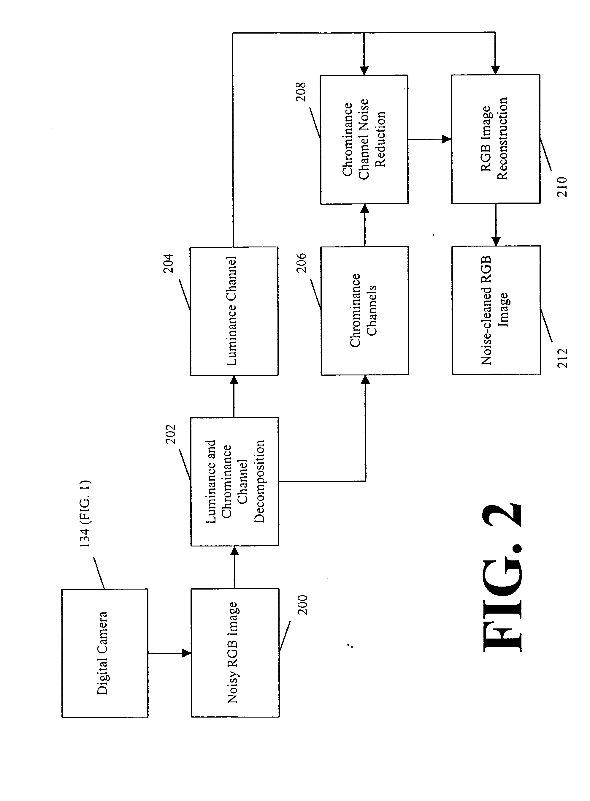
[0034]FIG. 10 is a high level diagram of an alternate embodiment. The digital camera 134 is responsible for creating an original red-green-blue (RGB) image that presumably contains noise (noisy RGB image) 200. This image is first decomposed into luminance and chrominance channels 202 as previously described. The luminance values together compose the luminance channel 204 and the chrominance values together compose the chrominance channels 206. The luminance and chrominance channels are then passed to the double-pass chrominance channel noise reduction operation 218 in which the noise in the chrominance channels is reduced. After block 218, the noise-reduced luminance and noise-reduced chrominance channels are converted back into RGB channels in the RGB image reconstruction step 210 as previously described. The results of block 210 compose the noise-cleaned RGB image for this embodiment 222.

[0035] The noise reduction algorithm disclosed in the preferred embodiment(s) of the present i...


PUM


Abstract

A method of reducing noise in a digital image produced by a digital imaging device, includes producing a luminance and at least one chrominance channel from a full-color digital image with each channel having a plurality of pixels and each such pixel has a value; producing an edge value from neighboring pixels in neighborhoods in the at least one chrominance channel; modifying the pixel value in the chrominance channel with an infinite impulse response filter responsive to the edge value of the corresponding pixel neighborhood to provide a modified chrominance channel; and producing a full-color digital image from the luminance channel and the modified chrominance channel, with reduced noise.

Description

FIELD OF THE INVENTION [0001] The invention relates generally to the field of digital image processing operations that are particularly suitable for use in all sorts of imaging devices. BACKGROUND OF THE INVENTION [0002] Video cameras and digital still cameras generally employ noise reduction operations as a standard component of their image processing chains. When the levels of noise are low and the number of pixels in the image modest, most any established noise reduction technique will be sufficient. When the levels of noise are high or the number of pixels in the image is large enough to tax the available computational resources, then the proper choice and implementation of noise reduction algorithms becomes more critical. One general approach is to use infinite impulse response (IIR) filter technology because of its strong noise cleaning capabilities and minimal memory usage requirements, i.e., computations are done in place with generally small pixel neighborhoods. Due to the ...

Claims


Application Information

Patent Timeline
Patent Type & Authority Applications(United States)
IPC IPC(8): H04N9/64
CPCH04N1/58H04N9/646G06T5/002G06T5/20G06T2207/10024G06T2207/20192
Inventor ADAMS, JAMES E. JR.MCMAHON, ANDREW K.DELLA NAVE, PIERREENGE, AMY D.
Owner EASTMAN KODAK CO
Why Eureka
Try Eureka