Off-axis paraboloid interferometric mirror with off focus illumination

an interferometric mirror and off-focus technology, applied in the field of measuring the surface topography of objects, can solve the problems of difficult implementation and interferometric comparison of objects with a known surface, and achieve the effect of less expensive optical elements and ligh

Inactive Publication Date: 2007-06-14
COHERIX
View PDF19 Cites 14 Cited by
  • Summary
  • Abstract
  • Description
  • Claims
  • Application Information

AI Technical Summary

Benefits of technology

[0013] It is an object of the invention to produce an interferom

Problems solved by technology

Interferometric comparison of objects with a known surface, as depicted by FIG. 1, has been difficult to implement for very large objects with surfaces with steps or slopes greater than a half wavelength of li

Method used


Image

  • Off-axis paraboloid interferometric mirror with off focus illumination
  • Off-axis paraboloid interferometric mirror with off focus illumination
  • Off-axis paraboloid interferometric mirror with off focus illumination

Examples


Embodiment Construction

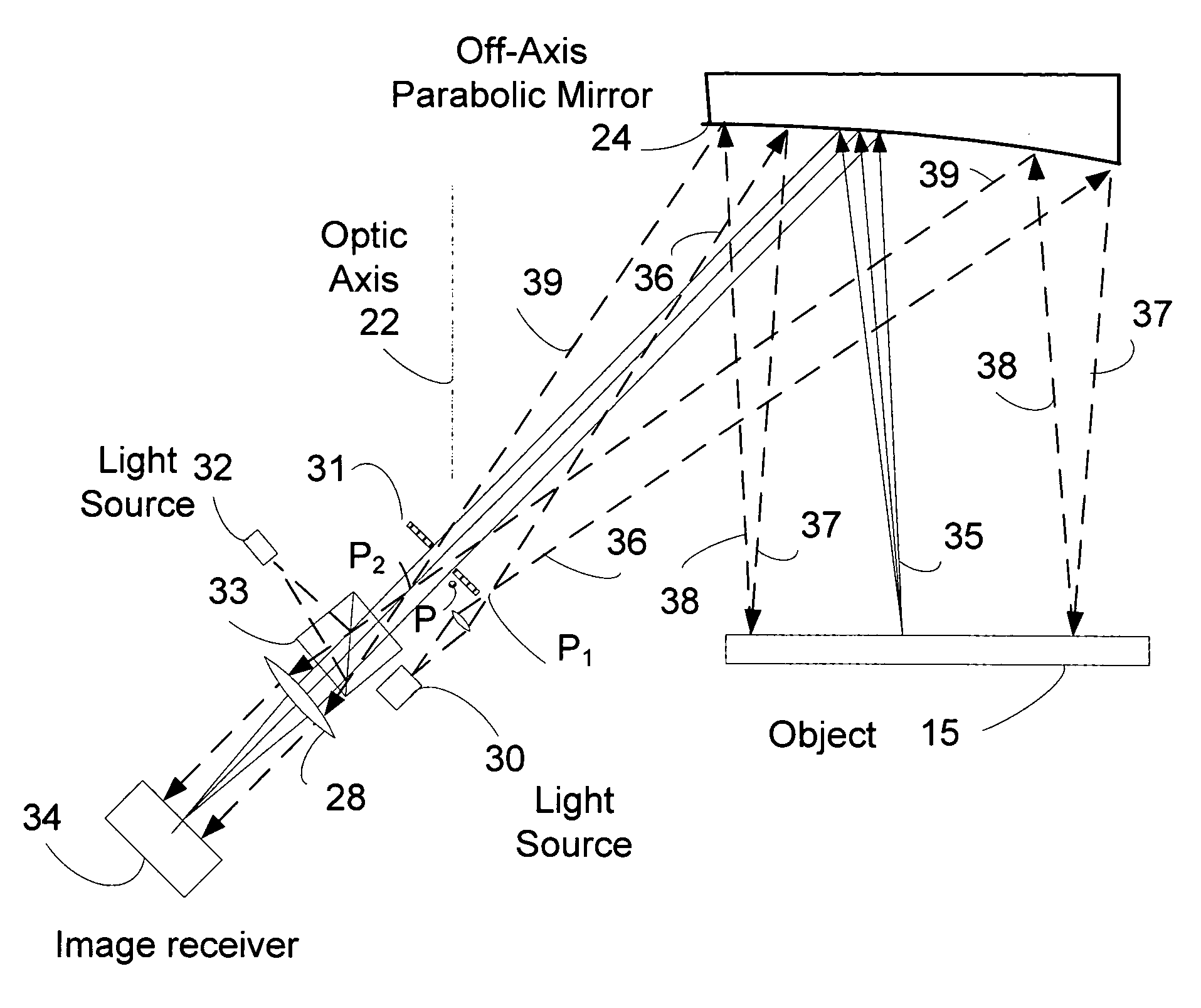
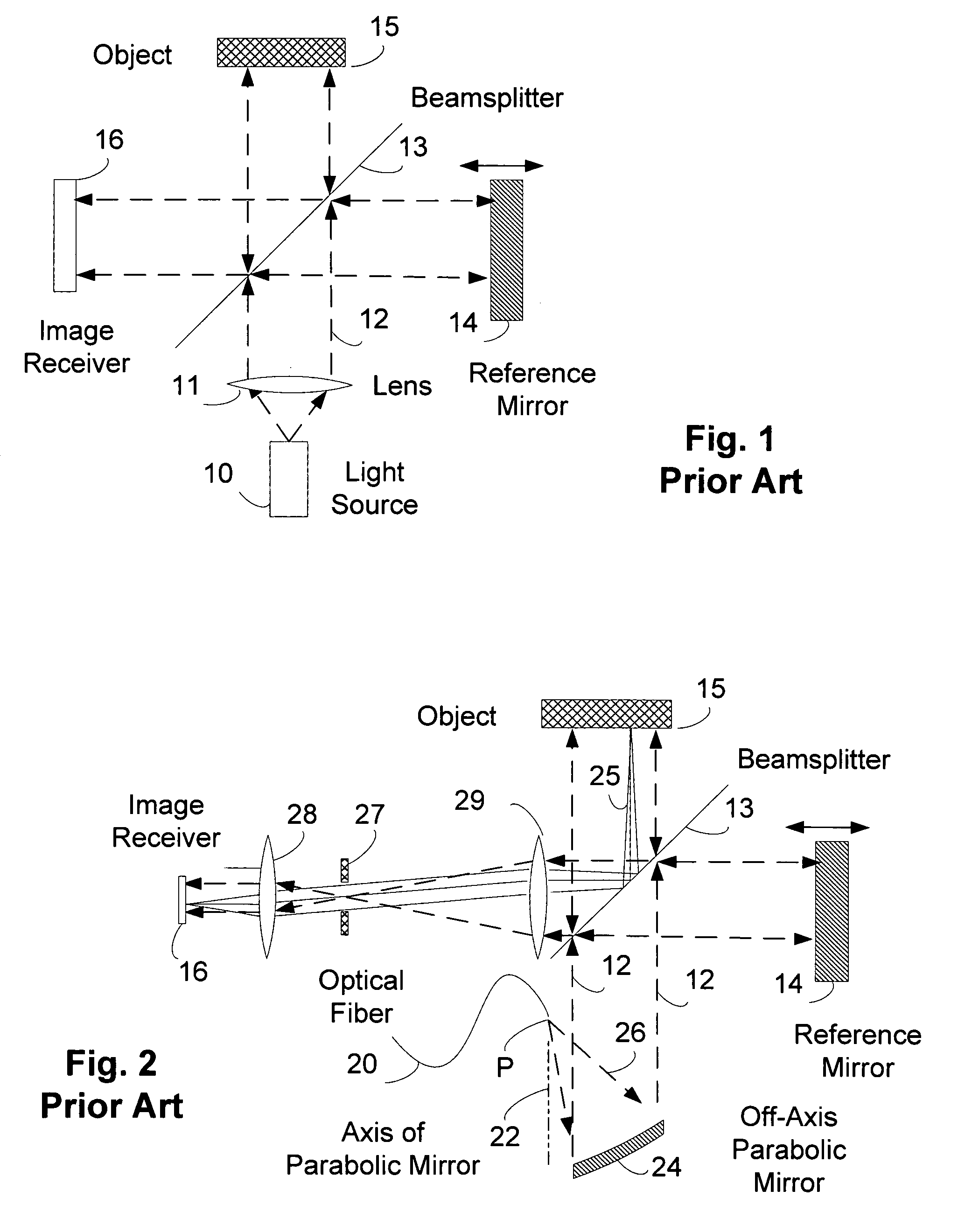
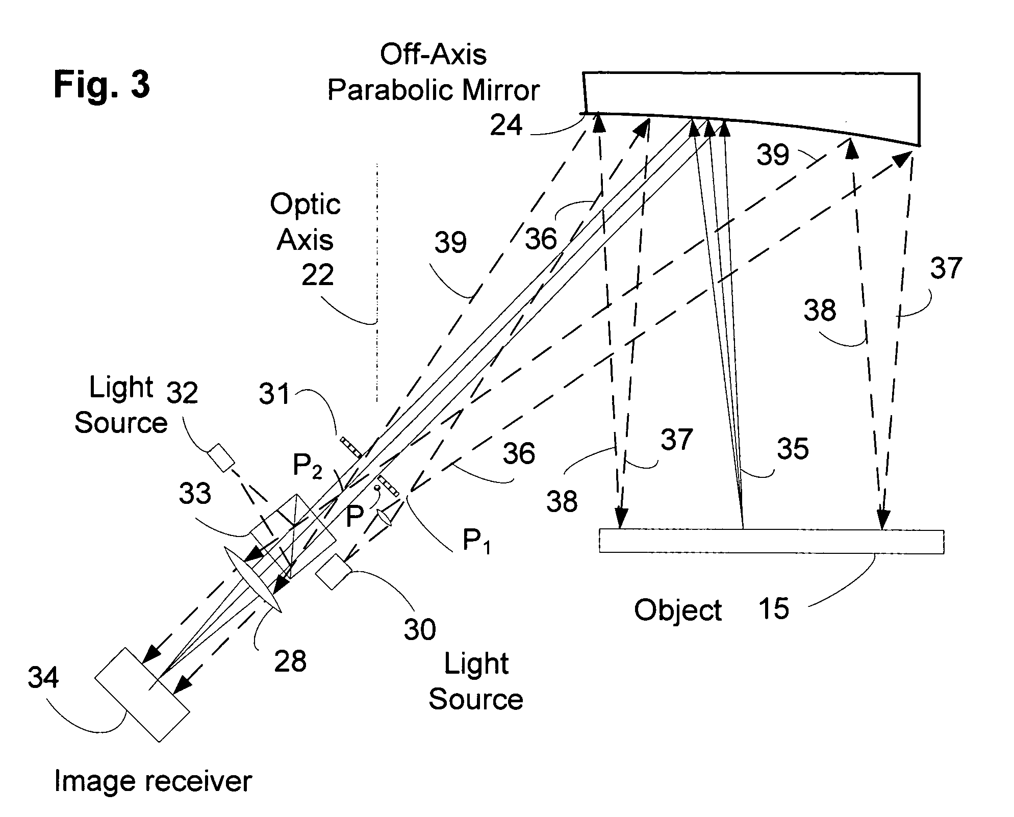
[0024]FIG. 1 shows a sketch of a prior art interferometer. The particular interferometer shown in FIG. 1 is conventionally called a Michelson interferometer, and has been used since the nineteenth century in optical experiments and measurements. A light source 10 produces light which is collimated by passing through a lens system 11 to produce a parallel beam of light 12 which passes to a beamsplitter 13. The beam of light 12 is partially reflected to a reference mirror 14 and partially transmitted to an object 15. Light reflected from the reference mirror 14 partially passes through the beamsplitter to an image receiver 16. Light reflected from the object is partially reflected from the beamsplitter 15 and is passed to the image receiver 16. The image receiver 16 may be film, or may be an electronic photodetector or a CCD or a CMOS array, or any other image receiver known in the art. The image receiver 16 may also include additional lenses, not shown, for imaging purposes.

[0025] I...


PUM


Abstract

An off axis paraboloid mirror is used to provide object illumination in an interferometric imaging system. The light from an object illumination light source diverges from a point apart from the focus point of the paraboloid, proceeds to the parabolic mirror surface, and is reflected as a nearly parallel beam to illuminate the object.

Description

FIELD OF THE INVENTION [0001] The field of the invention is the field of measuring surface topography of an object. BACKGROUND OF THE INVENTION [0002] Interferometry has been used for over a century to measure the surface topography of objects, typically optical components, and distances and small changes in such distances. With the advent of lasers having long coherence lengths and high brightness, the field has expanded greatly. Interferometric comparison of objects with a known surface, as depicted by FIG. 1, has been difficult to implement for very large objects with surfaces with steps or slopes greater than a half wavelength of light per resolution element of the imaging system, because the phase count is lost, and the height of the object surface is known only modulo λ / 2, where λ is the wavelength of light used for the interferometer. [0003] If a series of imaging interferograms are recorded with different wavelengths λi, the ambiguity in the phase may be resolved, and the he...

Claims


Application Information

Patent Timeline
IPC IPC(8): G01B11/02
CPCG01B9/02G01B11/2441G01B9/02007
Inventor KLOOSTER, ALEXALEKSOFF, CARL C.
Owner COHERIX
Why Eureka
Try Eureka