Print system, image supply device, print apparatus, and control method thereof

a technology of image supply and control method, applied in the direction of digital output to print units, instruments, computing, etc., to achieve the effect of confirming compatibility with direct printing function and safe confirmation of each other's devices

Inactive Publication Date: 2007-06-14
CANON KK
View PDF19 Cites 16 Cited by
  • Summary
  • Abstract
  • Description
  • Claims
  • Application Information

AI Technical Summary

Benefits of technology

[0027] According to the present invention, it is possible to safely confirm each other's devices by confirming compatibility with the direct print function and a new function without changing an existing communication protocol.
[0028] Other featur

Problems solved by technology

If this procedure is not completed, they recognize each ot

Method used


Image

  • Print system, image supply device, print apparatus, and control method thereof
  • Print system, image supply device, print apparatus, and control method thereof
  • Print system, image supply device, print apparatus, and control method thereof

Examples


second embodiment

[0119] In the second embodiment of the present invention, an example will be described in which a new function that is not incorporated in the direct print function is added as a cooperation function, thereby enhancing the direct print function. This cooperation function is a function of acquiring, from a CP, a current time used by a printer for, e.g., a printhead ink jet head recovery operation. The printhead ink jet head recovery operation is a known printhead maintenance means, and a description thereof will be omitted. How to make use of a current time for, e.g., the ink jet head recovery operation, has already been implemented as a function between a PC and a printer, and a description thereof will also be omitted.

[0120] PTP has date / time description areas such as the object “generation date / time”910 and “modification date / time”911 in the attribute information shown in FIG. 9. They are the generation (capturing) and modification dates / times of each object (e.g., photo). For th...

third embodiment

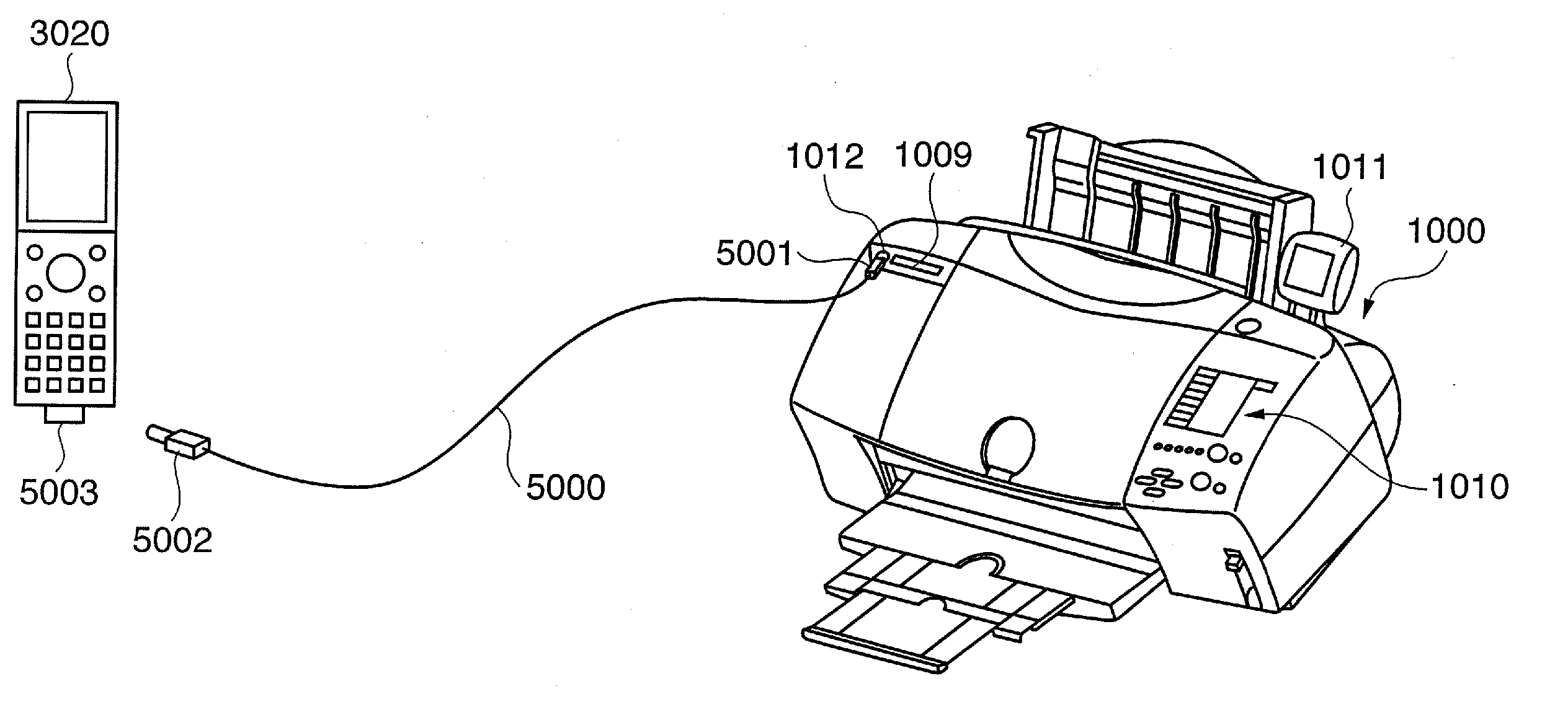
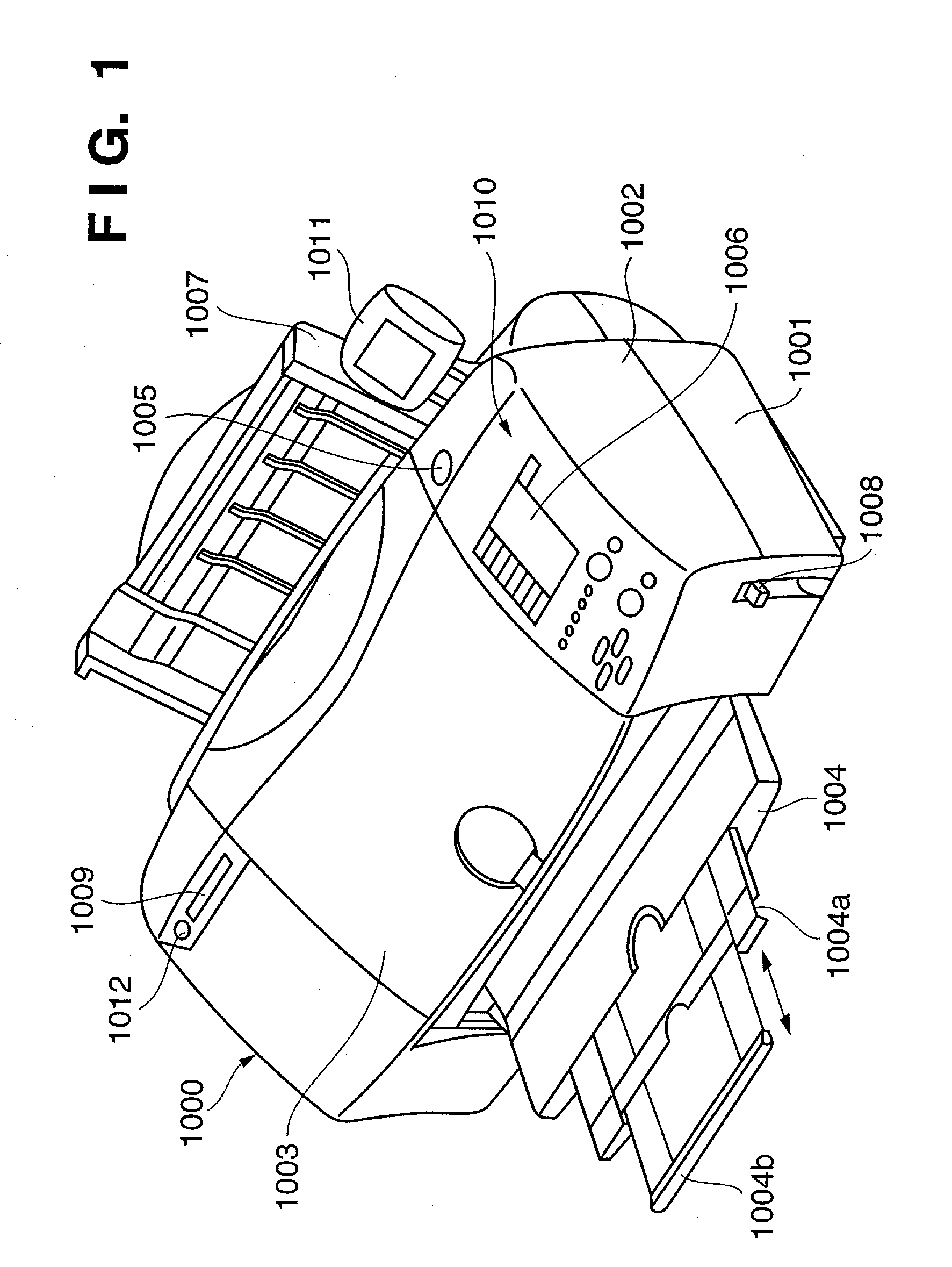
[0144] In the third embodiment of the present invention, an example will be described in which a CP and a printer share, as a cooperation function, the actual operation method of a function incorporated in the direct print function, thereby enhancing the direct print function. The arrangements of a PD printer 1000 and a CP 3020 according to the third embodiment are the same as in the above-described first embodiment, and a description thereof will be omitted.

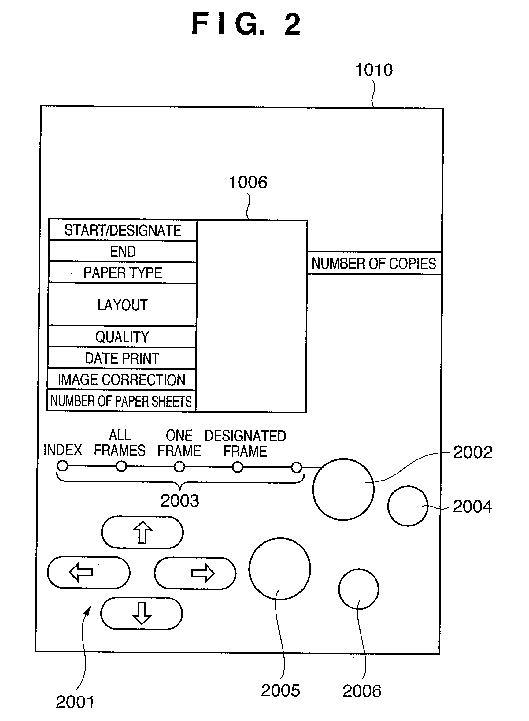
[0145] In the third embodiment, a layout print function of causing the PD printer 1000 to print, in one page, a plurality of images designated from the CP 3020 will be explained. An effective operation of such layout print will be described by exemplifying a case wherein a plurality of images with designated transmittances are composited and printed as one composite image. A detailed example is a frame print function of superimposing an image of, e.g., a frame on a photo and printing them.

[0146] In the third embodiment, the pr...

fourth embodiment

[0156]FIG. 18 is a flowchart for explaining an implementation example of a cooperation function between a CP 3020 and a PD printer 1000 according to the fourth embodiment of the present invention. The same step numbers as in FIG. 17 described above denote the same processes in FIG. 18, and a description thereof will be omitted. The arrangements of the PD printer 1000 and CP 3020 according to the fourth embodiment are the same as in the above-described first embodiment, and a description thereof will be omitted.

[0157] In step S72, the CP 3020 receives Capability from the PD printer 1000. The process advances to step S81 to determine whether the PD printer 1000 supports print of images with extensions “PNG” and “JPG”. If the PD printer 1000 does not support the formats, the process advances to step S82 to inhibit selection of “frame print” on the UI displayed on a display unit 35 of the CP 3020. If the PD printer 1000 supports images with the extensions “PNG” and “JPG”, the process a...


PUM


Abstract

There is provided a print system for transmitting and receiving a data object by a PTP between a camera-equipped mobile phone (CP) and a PD printer and printing an image by the PD printer according to image data supplied from the CP. First information indicating presence/absence of the direct print function capable of printing by transmitting image data from the CP directly to the PD printer and second information indicating presence/absence of the cooperated processing function with the CP and the PD printer are embedded in a data object which is transmitted and received. When it is judged that the received object contains the first and the second information, the CP and the printer are set to the direct print function and the cooperated processing function mode.

Description

TECHNICAL FIELD [0001] The present invention relates to a print system which has an image supply device and a print apparatus and causes the print apparatus to print an image based on image data supplied from the image supply device, the image supply device, the print apparatus, and a control method thereof. BACKGROUND ART [0002] So-called direct print is known in which a digital still camera (DSC) directly connects to a printer, an image held in the DSC is selected by using its display device, and the image file of the selected image is transmitted from the DSC to the printer to print the image. The direct print is advantageous because it allows easy print without intervention of a personal computer (PC). [0003] Patent reference 1 describes an arrangement in which a printer receives an image file from a DSC by using a general-purpose communication means provided in the printer to connect to a PC and the direct print is implemented. In patent reference 1, the DSC and printer exchang...

Claims


Application Information

Patent Timeline
IPC IPC(8): G06F3/12
CPCG06F3/1293H04N1/00278H04N2201/0015H04N2201/0072H04N2201/0084G06F3/1204G06F3/1209G06F3/1236G06F3/128
Inventor YAMADA, AKITOSHIAICHI, TAKAOMASUMOTO, KAZUYUKIHIRABAYASHI, HIROMITSU
Owner CANON KK
Why Eureka
Try Eureka