Lighting unit, electro-optic device, and electronic apparatus

a technology of electrooptic devices and light sources, applied in lighting devices, lighting and heating devices, instruments, etc., can solve the problems of disadvantageous insufficient image brightness, limited luminance level of illuminating light emitted from a backlight, and useless light emanating in the direction of the normal to the screen, etc., to achieve brightening an image and suppressing a decrease in light-use efficiency

Inactive Publication Date: 2007-06-14
EPSON IMAGING DEVICES CORP
View PDF9 Cites 20 Cited by
  • Summary
  • Abstract
  • Description
  • Claims
  • Application Information

AI Technical Summary

Benefits of technology

[0009] An advantage of some aspects of the invention is that there is provided a lighting unit that can suppress a decrease in light-use efficiency and brighten an image when viewed from a direction inclined with respect to the normal to a screen or different directions; and an electro-optic device.

Problems solved by technology

In particular, in mobile electronic apparatuses, such as cellular phones, personal digital assistants, and mobile computers, demands for a reduction in power consumption results in the limitation of the luminance level of illuminating light emitted from a backlight.
However, in cases where an image displayed on the screen is viewed from right and left oblique directions and where different images are viewed in different viewing angle ranges, light uselessly emanates in the direction of the normal to the screen, and the brightness of an image may be disadvantageously insufficient when the image is viewed from right and left oblique directions since the viewing angle distribution of luminance of light emitted from an lighting unit, such as a backlight, concentrates in a small-viewing-angle region (along or close to the direction of the normal to the screen) as described above.

Method used


Image

  • Lighting unit, electro-optic device, and electronic apparatus
  • Lighting unit, electro-optic device, and electronic apparatus
  • Lighting unit, electro-optic device, and electronic apparatus

Examples


embodiment

Related Embodiment

[0049]FIG. 9 shows data in relation to a known lighting unit that includes the planar light source 111 shown in FIGS. 1 and 2; the light diffuser 114 disposed adjacent to the emergent face of the planar light source 111; a first optical sheet OS1 shown in FIG. 5, the first optical sheet OS1 being disposed adjacent to the viewing side of the light diffuser 114 in such a manner that the smooth surface of the first optical sheet OS1 is disposed adjacent to the planar light source, the light-deflecting surface of the first optical sheet OS1 is disposed adjacent to the viewing side, and that the prismatic faces face toward the X-direction; a second optical sheet OS1 shown in FIG. 5, the second optical sheet OS1 being disposed adjacent to the viewing side of the first optical sheet OS1 in such a manner that the smooth surface of the second optical sheet OS1 is disposed adjacent to the planar light source, the light-deflecting surface of the second optical sheet OS1 is di...

first embodiment

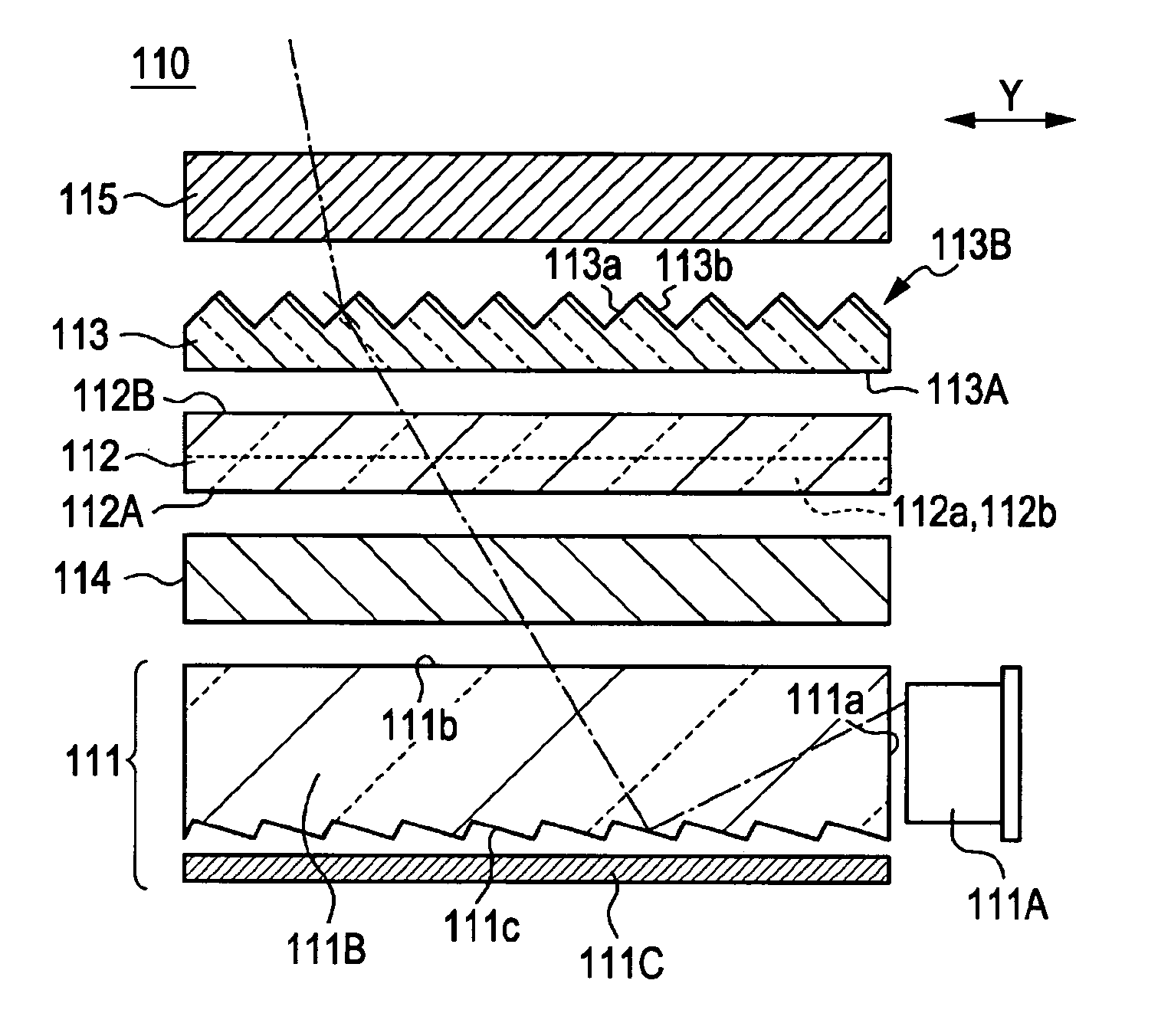
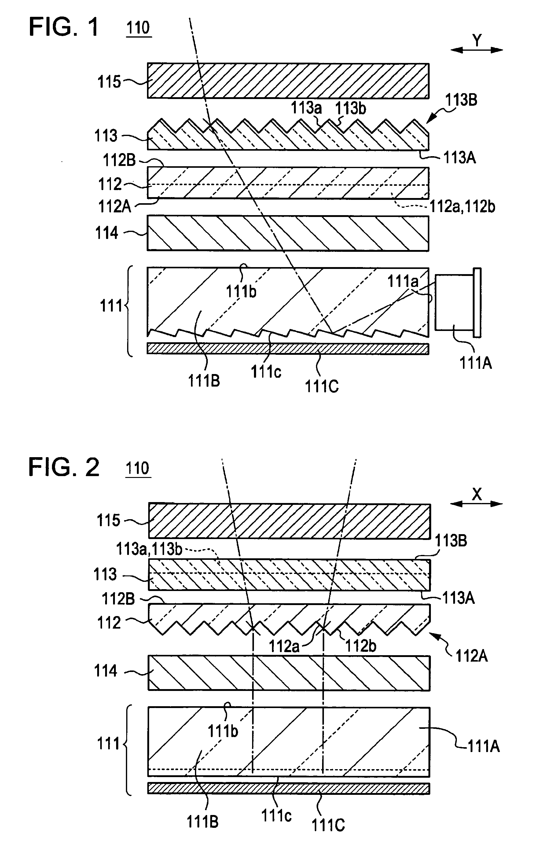
[0051]FIG. 10 shows data in relation to the lighting unit 110 according to a first embodiment, the lighting unit 110 including the planar light source 111 shown in FIGS. 1 and 2; the light diffuser 114 disposed adjacent to the emergent face of the planar light source 111; the first optical sheet 112 formed of the optical sheet OS1 shown in FIG. 5, the first optical sheet 112 being disposed adjacent to the viewing side of the light diffuser 114 in such a manner that the light-deflecting surface of the first optical sheet 112 is disposed adjacent to the planar light source, the smooth surface of the first optical sheet 112 is disposed adjacent to the viewing side, and that the prismatic faces face toward the X-direction; the second optical sheet 113 formed of the optical sheet OS1 shown in FIG. 5, the second optical sheet 113 being disposed adjacent to the viewing side of the first optical sheet 112 in such a manner that the smooth surface of the second optical sheet 113 is disposed a...

second embodiment

[0053]FIG. 11 shows data in relation to the lighting unit 110 according to a second embodiment, the lighting unit 110 including the planar light source 111 shown in FIGS. 1 and 2; the light diffuser 114 disposed adjacent to the emergent face of the planar light source 111; the first optical sheet 112 formed of the optical sheet OS2 shown in FIG. 6, the first optical sheet 112 being disposed adjacent to the viewing side of the light diffuser 114 in such a manner that the light-deflecting surface of the first optical sheet 112 is disposed adjacent to the planar light source, the smooth surface of the first optical sheet 112 is disposed adjacent to the viewing side, and that the prismatic faces face toward the X-direction; the second optical sheet 113 formed of the optical sheet OS2 shown in FIG. 6, the second optical sheet 113 being disposed adjacent to the viewing side of the first optical sheet 112 in such a manner that the smooth surface of the second optical sheet 113 is disposed ...


PUM


Abstract

A lighting unit includes a planar lighting component that emits illuminating light; a first light deflector having a prismatic face on one surface, the first light deflector being disposed on the planar lighting component; a second light deflector having a prismatic face on one surface, the second light deflector being disposed on the first light deflector, wherein the one surface of the first light deflector is opposite the one surface of the second light deflector, and the direction of tilt of the prismatic face of the first light deflector is perpendicular to the direction of tilt of the prismatic face of the second light deflector.

Description

[0001] The entire disclosure of Japanese Patent Application No. 2005-357258, filed Dec. 12, 2005 is expressly incorporated by reference herein. BACKGROUND [0002] 1. Technical Field [0003] The present invention relates to a lighting unit, an electro-optic device, and an electronic apparatus. In particular, the invention relates to the structure of a lighting unit having a light-deflecting surface provided with tilted prismatic faces. [0004] 2. Related Art [0005] Various types of electro-optic devices, such as liquid-crystal displays, included in electronic apparatuses having various displays have viewing-angle properties in which light that emerges from a screen in the direction of the normal to the screen has the maximum luminance level, and a luminance level decreases with increasing exit angle (angle with respect to the normal to the display). In particular, in mobile electronic apparatuses, such as cellular phones, personal digital assistants, and mobile computers, demands for a ...

Claims


Application Information

Patent Timeline
Patent Type & Authority Applications(United States)
IPC IPC(8): F21V7/04
CPCG02B6/0053
Inventor SAKAI, TOYOHIRO
Owner EPSON IMAGING DEVICES CORP
Why Eureka
Try Eureka