Method and apparatus for allocating transmission power in communication system with multiple antennas
- Summary
- Abstract
- Description
- Claims
- Application Information
AI Technical Summary
Benefits of technology
Problems solved by technology
Method used
Image

Examples
first embodiment
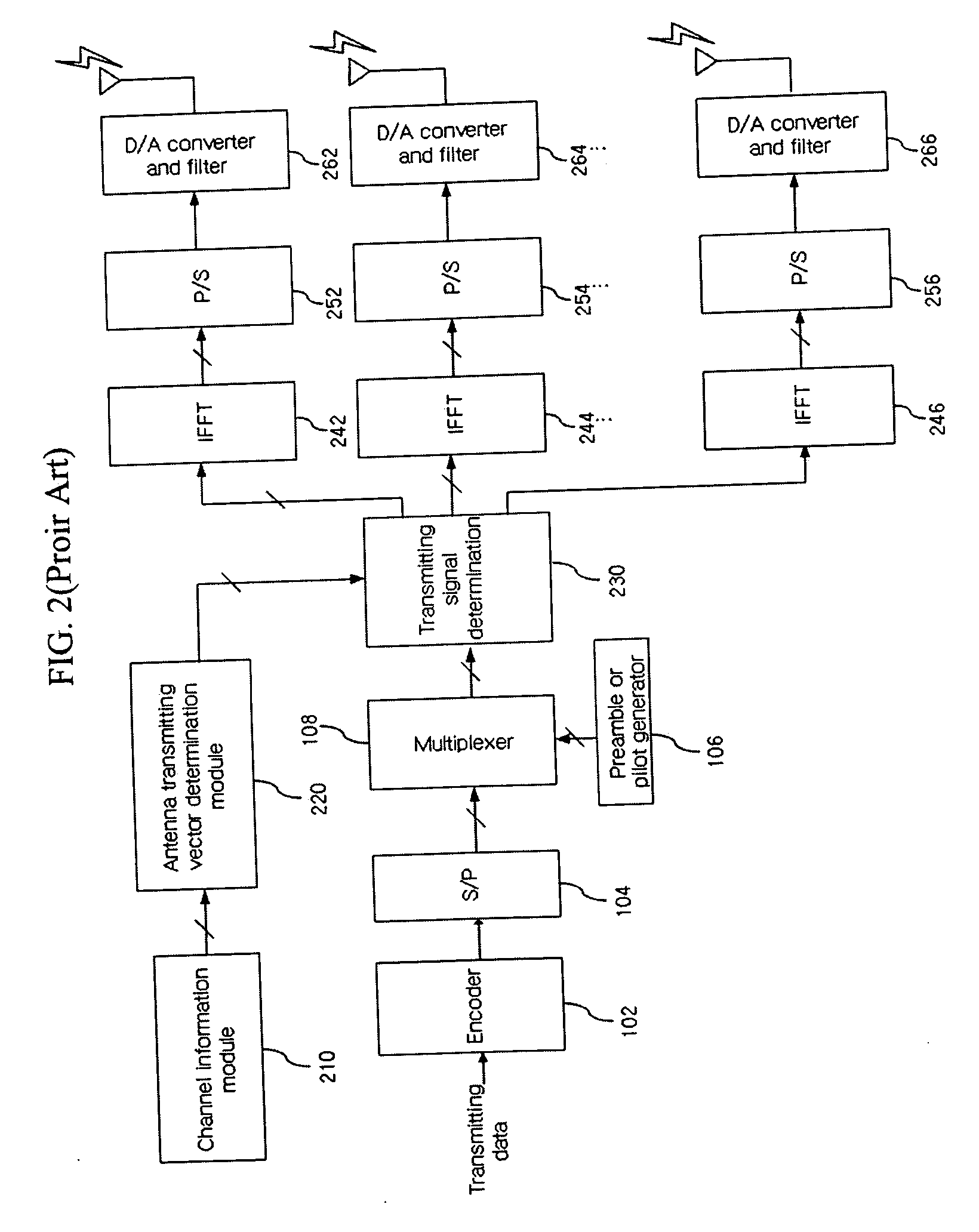
[0047] A method for calculating transmission power weight for each group by using channel information according to the present invention will be described with reference to FIG. 2 and FIG. 5. Referring to FIG. 2, in order to explain the method for calculating transmission power weight for each group by using channel information, qg,i,m denoting i-th subcarrier of g-th group and transmission signal of m-th group can be obtained by the following Equation (4):
qg,i,m=wg,msg,i (4)
[0048] In addition, a received signal of i-th subcarrier of g-th group that is allocated to an OFDM terminal can be obtained by the following Equation (5). rg,i=∑m=1Mhg,i,mwg,msg,i+ng,i(5)
[0049] In Equation (5), rg,l denotes a received signal of i-th (i=1, 2, . . . , l) subcarrier of g-th (g=1, 2, . . . , G) group, and Gl denotes the number of subcarriers allocated to a terminal. The hg,i,m denotes a channel for a m-th transmission antenna of i-th subcarrier of g-th group, wg,m denotes a transmission weigh...
second embodiment
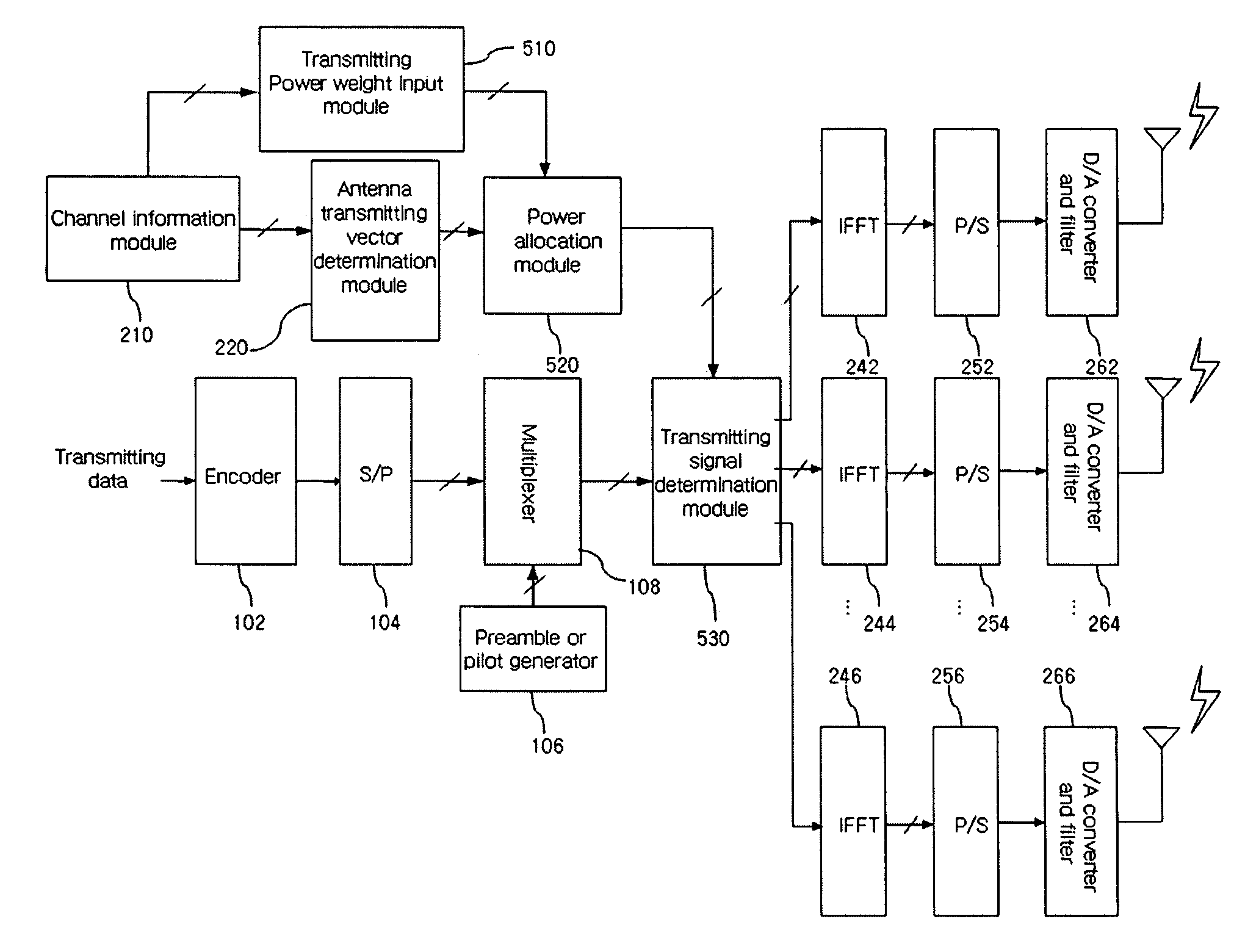
[0060]FIG. 6 is a diagram illustrating a transmission block according to the present invention.
[0061] When the code book is used for calculating the transmission power weight for each group, it is assumed that J bit is used for the transmission weight wg,m for each antenna of each group. For example, the J bit denotes 3 bit in FIG. 3. In addition, K bit is additionally used so as to feedback the transmission power weight that is allocated to each group.
[0062] When Pmax denotes power of a group that has maximum power value (∑m-1Mhg,m2)
among G groups allocated to the terminal, the weight for each group can be obtained by the normalization to Pmax. Here, the normalized weight (δg) for each group is represented by the following Equation (11), δg=hg2Pmax(11)
[0063] wherein δg denotes amounts from 0 to 1.
[0064] When the δg is quantized to K bit, the feedback for the δg can be performed by dividing amounts from 0 to 1 into 2K units. In addition, the intervals between units can be clas...
third embodiment
[0076] When a plurality of transmission antennas are used, the amplifier having amplification characteristic M times greater than the number of the transmission antenna becomes necessary. Accordingly, hardware cost increases. However, according to the present invention to be described with reference to FIG. 7, the transmission power weight is allocated by limiting the maximum transmission power for each antenna in order to reduce hardware cost. When the maximum transmission power ratio is β (0<β≦1), β can be determined by the hardware realization. When the number of the transmission antenna is M, and the transmission power is limited as in the method not using channel information, β equals 1 / M.
[0077] Therefore, the transmission power Pm normalized to the group G entirely using m-th antenna can be obtained by the following Equation (15). Pm=1G∑g=1G(αghg,m2)(15)
[0078] When the normalized maximum transmission power ratio for each antenna is limited to β, the transmission power weig...
PUM
 Abstract
Description
Claims
Application Information
 - Generate Ideas
- Intellectual Property
- Life Sciences
- Materials
- Tech Scout
- Unparalleled Data Quality
- Higher Quality Content
- 60% Fewer Hallucinations
Browse by: Latest US Patents, China's latest patents, Technical Efficacy Thesaurus, Application Domain, Technology Topic, Popular Technical Reports.
© 2025 PatSnap. All rights reserved.Legal|Privacy policy|Modern Slavery Act Transparency Statement|Sitemap|About US| Contact US: help@patsnap.com