Physical coding sublayer apparatus and Ethernet layer architecture for network-based tunable wavelength passive optical network system

Inactive Publication Date: 2007-06-14
ELECTRONICS & TELECOMM RES INST
View PDF7 Cites 21 Cited by
  • Summary
  • Abstract
  • Description
  • Claims
  • Application Information

AI Technical Summary

Benefits of technology

[0041] According to an aspect of the present invention, there is provided a PCS (physical coding sublayer) apparatus for a network-based T-PON (tunable-wavelength passive optical network) system of Ethernet including an ONT (optical network terminal) having a tunable-wavelength light source, the PCS apparatus including: a wavelength monitoring unit extracting wavelength information from a digital frame signal transmitted from the ONT and monitoring whether the wavelength information is identical with wavelength information allocated to a light source of the ONT; and an auto-identification unit, if the wavelength information is not identical with the wavelength information allocated to the light source of the ONT, adding wavelength control information to the digital frame signal and transmitting the wavelength control information to the ONT.
[0042] According to another aspect of the present invention, there is provided an Ethernet layer architecture for a network-based T-PON (tunable-wavelength passive optical network) system of Ethernet including an ONT (optical network terminal) having a tunable-wavelength light source, the Ethernet layer architecture including: a PMD (physical medium dependent) receiver receiving an optical signal transmitted from the ONT; a PCS (physical coding sublayer) extracting wavelength information from the received optical signal, monitoring whether the wavelength information is identical with wavelength information allocated to a light source of the ONT, and if the wavelength information is not identical with the wavelength information allocated to the light source of the ONT, adding wavelength control information to the digital frame signal; a PMA (physical medium attachment) changing the digital frame signal to which the wavelength control information is added and which has a parallel stru

Problems solved by technology

In WDM-PON, there are problems that a price of a system increases and a businessman should sort and control different ONTs.
However, the optical layer initialization method should provide an additional seed

Method used


Image

  • Physical coding sublayer apparatus and Ethernet layer architecture for network-based tunable wavelength passive optical network system
  • Physical coding sublayer apparatus and Ethernet layer architecture for network-based tunable wavelength passive optical network system
  • Physical coding sublayer apparatus and Ethernet layer architecture for network-based tunable wavelength passive optical network system

Examples


Embodiment Construction

[0055] The present invention will be described more fully hereinafter with reference to the accompanying drawings in which exemplary embodiments of the invention are shown.

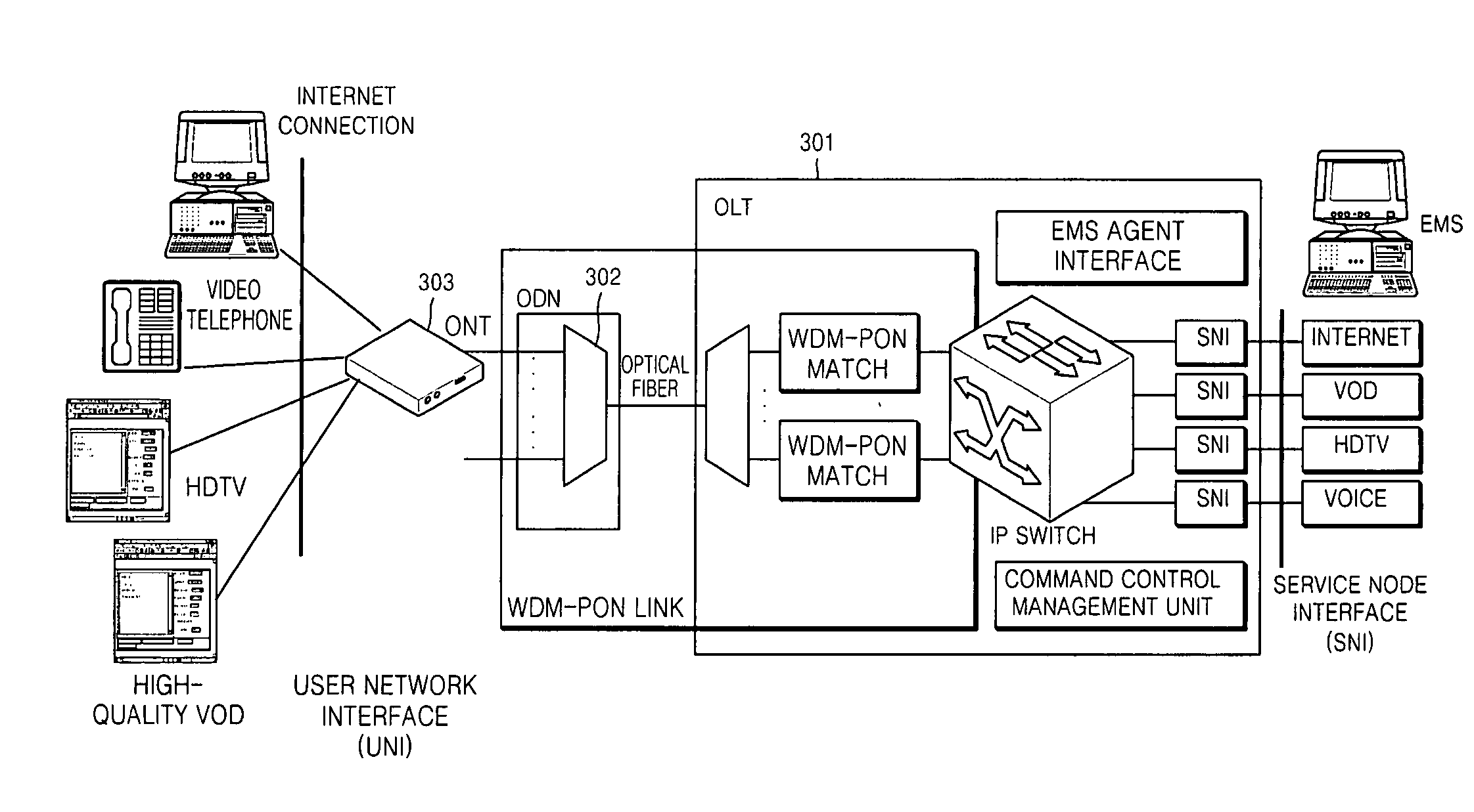
[0056]FIG. 3 illustrates a network structure and functions of a tunable-wavelength passive optical network (T-PON) system.

[0057] Like the configuration of a conventional optical subscriber network, an optical line terminal (OLT) 301 includes a plurality of match cards having separate wavelengths. A downstream optical signal output from each match card is multiplexed as one optical cable through an output multiplexer (OMUX).and is transmitted to a subscriber terminal.

[0058] On the contrary, an upstream optical signal received from the OLT 301 is demultiplexed through an output demultiplexer (ODEMUX) and is separated into several optical signals. That is, single mode light sources modulate lights having N wavelengths for N subscriber terminals into respective downstream signals λi(i:1˜N), and an optical receiver ...


PUM


Abstract

Provided are a physical coding sublayer (PCS) apparatus and an Ethernet layer architecture for a network-based tunable-wavelength passive optical network (T-PON) system employing an Ethernet communications technology, and more particularly, to a PCS apparatus and an Ethernet layer architecture for supporting a series of initialization function of allocating wavelengths between an optical line terminal (OLT) and an optical network terminal (ONT) and arranging the allocated wavelengths. A PCS layer transmits and allocates wavelength information such that wavelengths for setting a link between an OLT and an ONT are allocated, optical wavelengths within the ONT are observed while a system operates to allow continuous control so that operating of the system can be stably maintained.

Description

CROSS-REFERENCE TO RELATED PATENT APPLICATIONS [0001] This application claims the benefits of Korean Patent Application No. 10-2005-0121000, filed on Dec. 9, 2005, and Korean Patent Application No. 10-2006-0085820, filed on Sep. 6, 2006, in the Korean Intellectual Property Office, the disclosures of which are incorporated herein in their entirety by reference. BACKGROUND OF THE INVENTION [0002] 1. Field of the Invention [0003] The present invention relates to a physical coding sublayer (PCS) apparatus and an Ethernet layer architecture for a network-based tunable-wavelength passive optical network (T-PON) system employing an Ethernet communications technology, and more particularly, to a PCS apparatus and an Ethernet layer architecture for supporting a series of initialization function of allocating wavelengths between an optical line terminal (OLT) and an optical network terminal (ONT) and arranging the allocated wavelengths. [0004] 2. Description of the Related Art [0005] As the s...

Claims


Application Information

Patent Timeline
IPC IPC(8): H04B10/20
CPCH04J14/0226H04J14/0282H04Q11/0067H04Q2011/0018H04Q2011/0079H04Q2011/0086H04J14/0246H04J14/025
Inventor LEE, KANG BOKYOON, HYEON HOKIM, TAE YEONYOO, JEONG JUKIM, BYOUNG WHI
Owner ELECTRONICS & TELECOMM RES INST
Why Eureka
Try Eureka