
Bone anchor

Inactive Publication Date: 2007-06-14
IST INNOVATIVE SHOULDER TECH
View PDF19 Cites 20 Cited by
  • Summary
  • Abstract
  • Description
  • Claims
  • Application Information

AI Technical Summary

Benefits of technology

[0008] Therefore, there is a need for a bone anchor of the type described at the outset with improved properties regarding reliability, ease of handling and secure anchoring in the bone.
[0010] As it will be evident from the description which follows and the drawings, the bone anchor described here can be conceived to be a striking anchor, which has an outside thread near the proximal end. As a result of this, the bone anchor can be set into the bone very rapidly. The outside thread fixes the bone anchor in the corticalis. In spite of that, if needed, it can be removed again relatively easily.
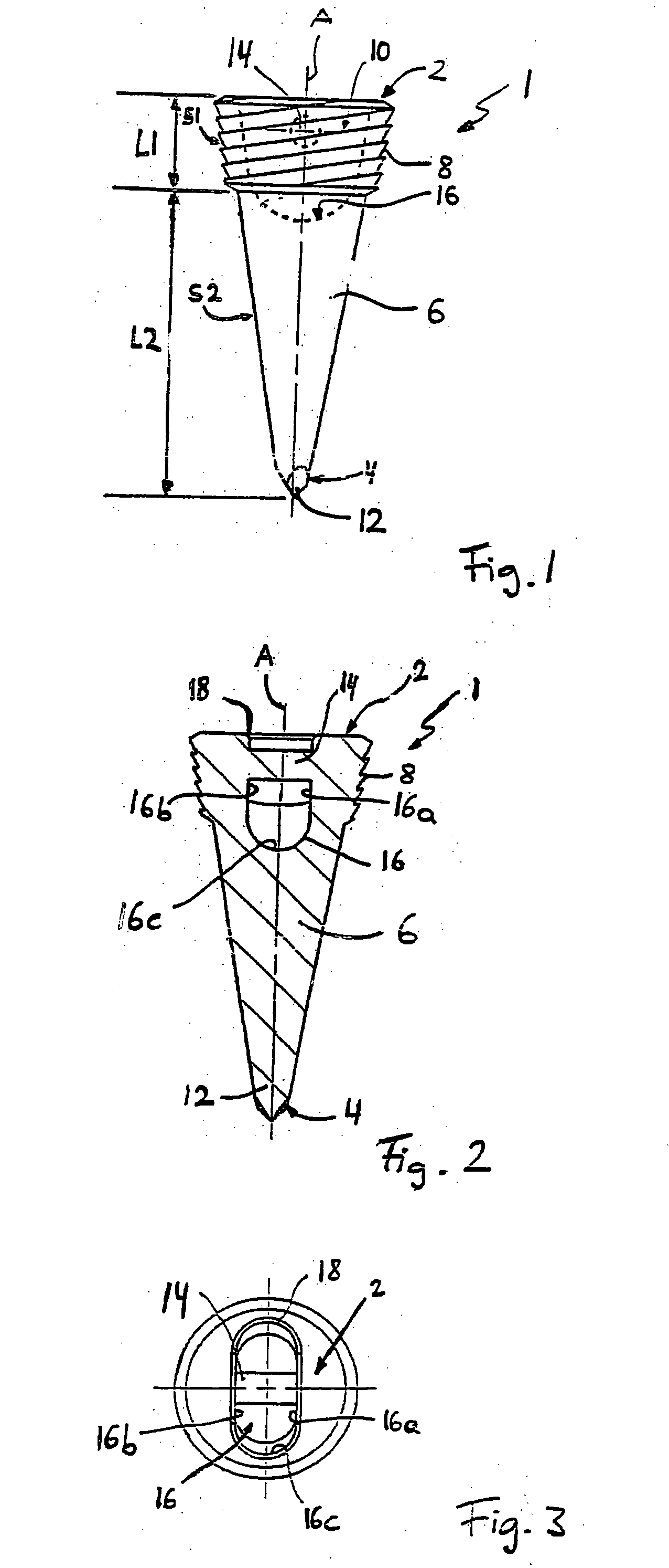
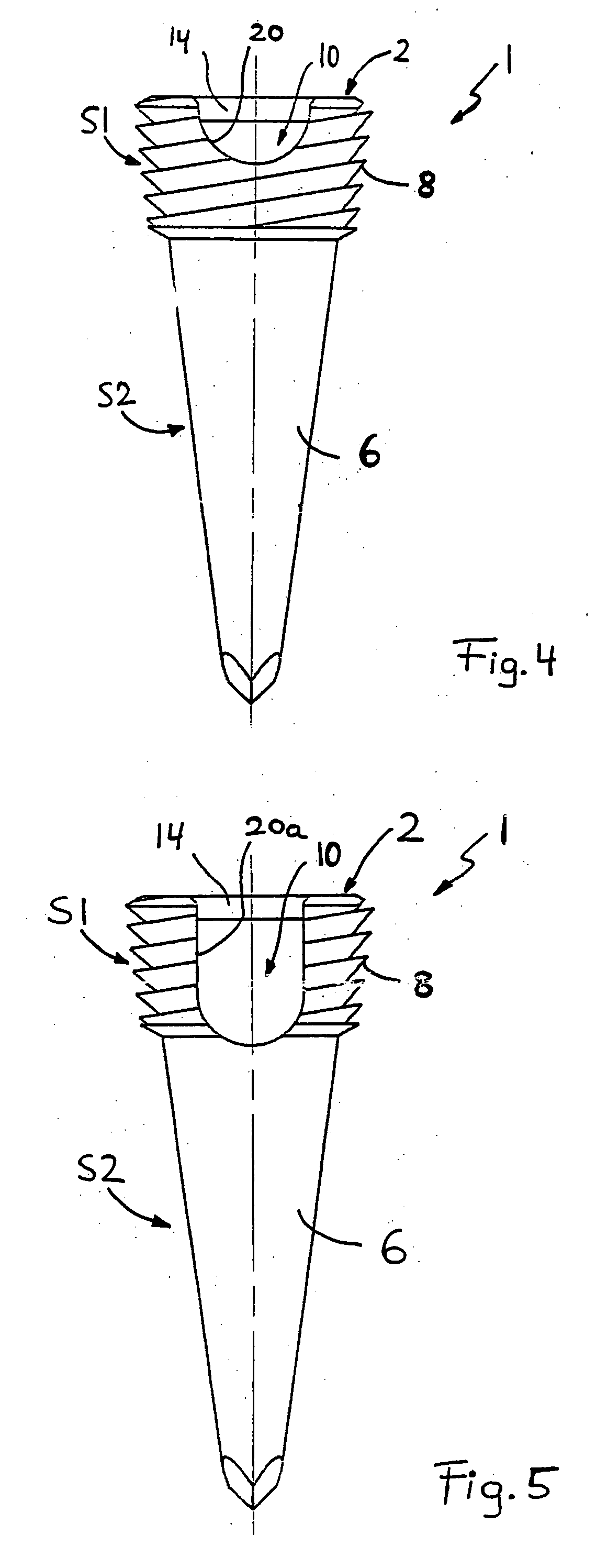
[0011] The device which is at the proximal end is designed so that it makes easier threading of the holding thread possible and that no edges are present at which the holding thread may tear. The device ends with the proximal end of the bone anchor, as a result of which the implanted bone anchor ends essentially at the outside surface of the bone. In this way, guiding of the holding thread over an edge of the bone and breaking of the thread there can be avoided.

Problems solved by technology

Due to the relatively small cross-section of the head part, there is a danger that the head part and thus the thread holder, will be screwed off during the setting of the bone anchor.
Although in the bone anchor known from EP 829 233 A1 the insertion slit in the screw body is sunk so that the danger of it becoming screwed off no longer exists, the need to thread the thread into the groove from the tip to the proximal end seems not very practicable.
However, in the case of this anchor the disadvantage is that the set anchor cannot be removed again or is difficult to remove because of the wedging of the barbs.

Method used


Image

  • Bone anchor
  • Bone anchor
  • Bone anchor

Examples


Embodiment Construction

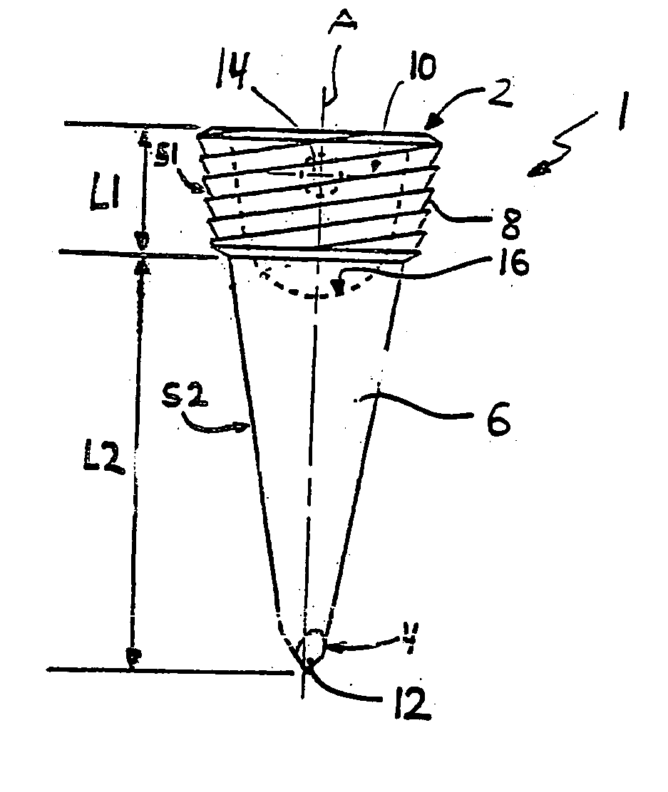
[0017]FIG. 1 shows a practical example of a bone anchor 1, which serves to secure soft tissues on a bone. The bone anchor 1 has a body 6 which extends symmetrically around a longitudinal axis A from a proximal end 2 to a distal end 4. Body 6 has a section S1 of a length L1, which, starting from proximal end 2 extends in the direction of the distal end 4. Section S1 has an outside thread 8. The body 6 also has a section S2 of a length L2, which is attached to section S1 and extends to the distal end 4. Section S2 does not have a thread.

[0018] As further explained below, the length L1 of section S1 is chosen so that the outside thread 8 screws into the corticalis of the bone. In a practical example, the length L1 is about 3 mm and the length L2 about 6 mm. The values for the length L1 may vary, but they correspond to the thicknesses that typically exist in humans in the corticalis. The total length of the bone anchor 1 can be about 5 to about 10 mm.

[0019] In the practical example sh...


PUM


Abstract

A bone anchor is provided having has a body with a proximal end and a distal end, a first section starting from the proximal end, with an outside thread and also a thread-free second section adjoining to it. The first section has a length that is adjusted to the thickness of the corticalis. The bone anchor has a device at the proximal end, the device extending from the proximal end into the body and serves to hold a holding thread.

Description

BACKGROUND OF THE INVENTION [0001] The invention concerns a device for attaching soft tissues to a human or animal bone. [0002] In various human and veterinary surgical processes, soft tissues, for example, tendons and ligaments, must be attached to a bone. The attachment can become necessary when, for example, due to an accident or a degenerative process, a tendon becomes separated from the bone and then the tendon will have to be attached to it again. In surgery various devices are used for this, which are frequently called bone anchors, as in the description below. The bone anchor is attached to an exposed bone in a preparatory step. With a suture material (for example, holding thread) attached to or guided into the bone anchor, for example, the tendon is attached to the bone anchor and thus to the bone. [0003] A known bone anchor is the Statak® bone anchor made by the company Zimmer, Inc. This bone anchor has a cylindrical screw body with an outside thread, a distal wedge-shaped...

Claims


Application Information

Patent Timeline
IPC IPC(8): A61B17/58
CPCA61B17/0401A61B17/863A61B2017/0412A61B2017/0414A61B2017/044
Inventor KROPF, PHILIPLEUZINGER, JAN
Owner IST INNOVATIVE SHOULDER TECH
Learn More