Steering control device

Pending Publication Date: 2021-04-01
JTEKT CORP
View PDF11 Cites 0 Cited by
  • Summary
  • Abstract
  • Description
  • Claims
  • Application Information

AI Technical Summary

Benefits of technology

[0023]With this configuration, when the limit position determination angles on both the right and left sides are acquired, it is possible to rapidly set the end-position-corresponding angles on both the right and left sides which accurately corresponds to actual end angles without waiting until a plurality of limit position determination angles on the right or left side is acquired by comparing the stroke width with the stroke threshold value. When a plurality of limit position determination angles on only the right or left side is acquired, the

Problems solved by technology

As a result, when the stored end-position-corresponding angle is displaced to a neutral steering position side with respect to the actual end angle, there is concern that an increase in a steering reaction component due to performing of end contact relaxation control or a limitation of the current command value will be insufficient and an impact of the end contact will not be able to be satisfactorily relaxed.
Accordi

Method used


Image

  • Steering control device
  • Steering control device
  • Steering control device

Examples


Example

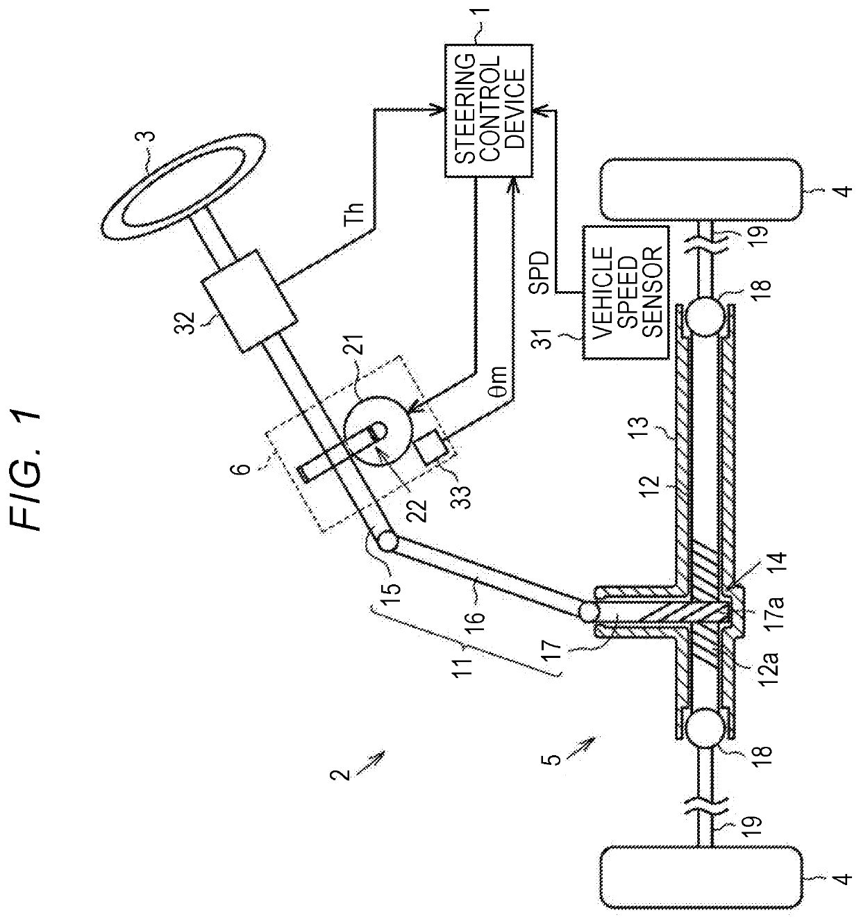
[0037]Hereinafter, a steering control device according to a first embodiment of the disclosure will be described with reference to the accompanying drawings. As illustrated in FIG. 1, an electric power steering system (EPS) 2 which is a steering system to be controlled by a steering control device 1 includes a steering mechanism 5 that turns turning wheels 4 based on a driver's operation of a steering wheel 3. The EPS 2 further includes an EPS actuator 6 which is an actuator that applies an assist force for assisting a steering operation to the steering mechanism 5.

[0038]The steering mechanism 5 includes a steering shaft 11 to which the steering wheel 3 is fixed, a rack shaft 12 which is a turning shaft connected to the steering shaft 11, a rack housing 13 which is a housing into which the rack shaft 12 is inserted such that it can reciprocate, and a rack and pinion mechanism 14 that converts a rotational motion of the steering shaft 11 to a translational motion of the rack shaft 12...

Example

Second Embodiment

[0153]A steering control device according to a second embodiment will be described below with reference to the accompanying drawings. This is mainly different from the first embodiment in only calculate of the second determination variance value Vd2 in the update permitting unit 95. Accordingly, for the purpose of convenience of description, the same elements will be referred to by the same reference signs as in the first embodiment and description thereof will be omitted.

[0154]When a plurality of limit position determination angles θi on the left side is acquired, the update permitting unit 95 in this embodiment arranges and holds the limit position determination angles θi in increasing order of the pinion shaft torque Tp. When the limit position determination angles θi corresponding to a predetermined acquisition number nth are acquired, the update permitting unit 95 selects the limit position determination angles θi corresponding to a predetermined calculation nu...


PUM


Abstract

A steering control device includes an electronic control unit. The electronic control unit detects an absolute steering angle. The electronic control unit controls driving of a motor. The electronic control unit determines whether movement of a turning shaft to one of right and left sides has been limited by an end contact or execution of end contact relaxation control. The electronic control unit acquires a plurality of limit position determination angles corresponding to the absolute steering angle. The electronic control unit permits update of an end-position-corresponding angle. The electronic control unit updates the end-position-corresponding angle stored in the electronic control unit.

Description

CROSS-REFERENCE TO RELATED APPLICATION[0001]This application claims priority to Japanese Patent Application No. 2019-175763 filed on Sep. 26, 2019 and Japanese Patent Application No. 2019-175764 filed on Sep. 26, 2019, each incorporated herein by reference in its entirety.BACKGROUND1. Technical Field[0002]The disclosure relates to a steering control device.2. Description of Related Art[0003]An electric power steering system (EPS) including an actuator with a motor as a drive source is known as a vehicular steering system. As such an EPS, there is an EPS that acquires a steering angle of a steering wheel as an absolute angle including a range exceeding 360° and performs various types of control based on the steering angle. As examples of such control, for example, Japanese Unexamined Patent Application Publication No. 2015-20506 (JP 2015-20506 A) and Japanese Patent No. 5962881 (JP 5962881 B) disclose that end contact relaxation control for relaxing an impact of a so-called end conta...

Claims


Application Information

Patent Timeline
IPC IPC(8): B62D5/04B62D15/02
CPCB62D5/0469B62D15/0225B62D5/0421B62D5/0463B62D3/12B62D6/00
Inventor YAMAGUCHI, TAKAFUMITOKO, TAKAHIROKATAOKA, NOBUAKIEZAKI, YUKINOBU
Owner JTEKT CORP
Why Eureka
Try Eureka