Telescoping bifurcated stent

a telescopic, bifurcated technology, applied in the field of implantable medical devices, can solve the problems of many prior art stents not being wholly satisfactory for us

Inactive Publication Date: 2007-06-14
BOSTON SCI SCIMED INC
View PDF99 Cites 85 Cited by
  • Summary
  • Abstract
  • Description
  • Claims
  • Application Information

AI Technical Summary

Benefits of technology

[0028] At least one embodiment of the invention is directed to a stent with a ring bifurcation branch in which a ring contains a ratchet configuration which allows it to either increase or decrease its circumference by moving a loc

Problems solved by technology

Many prior art stents however are not wholly satisfactory for use where the site of desired application of the stent is juxtaposed or extends

Method used


Image

  • Telescoping bifurcated stent
  • Telescoping bifurcated stent
  • Telescoping bifurcated stent

Examples


Embodiment Construction

[0063] The invention will next be illustrated with reference to the figures wherein the same numbers indicate similar elements in all figures. Such figures are intended to be illustrative rather than limiting and are included herewith to facilitate the explanation of the apparatus of the present invention.

[0064] For the purposes of this disclosure, like reference numerals in the figures shall refer to like features unless otherwise indicated.

[0065] Depicted in the figures are various aspects of the invention. Elements depicted in one figure may be combined with, or substituted for, elements depicted in another figure as desired.

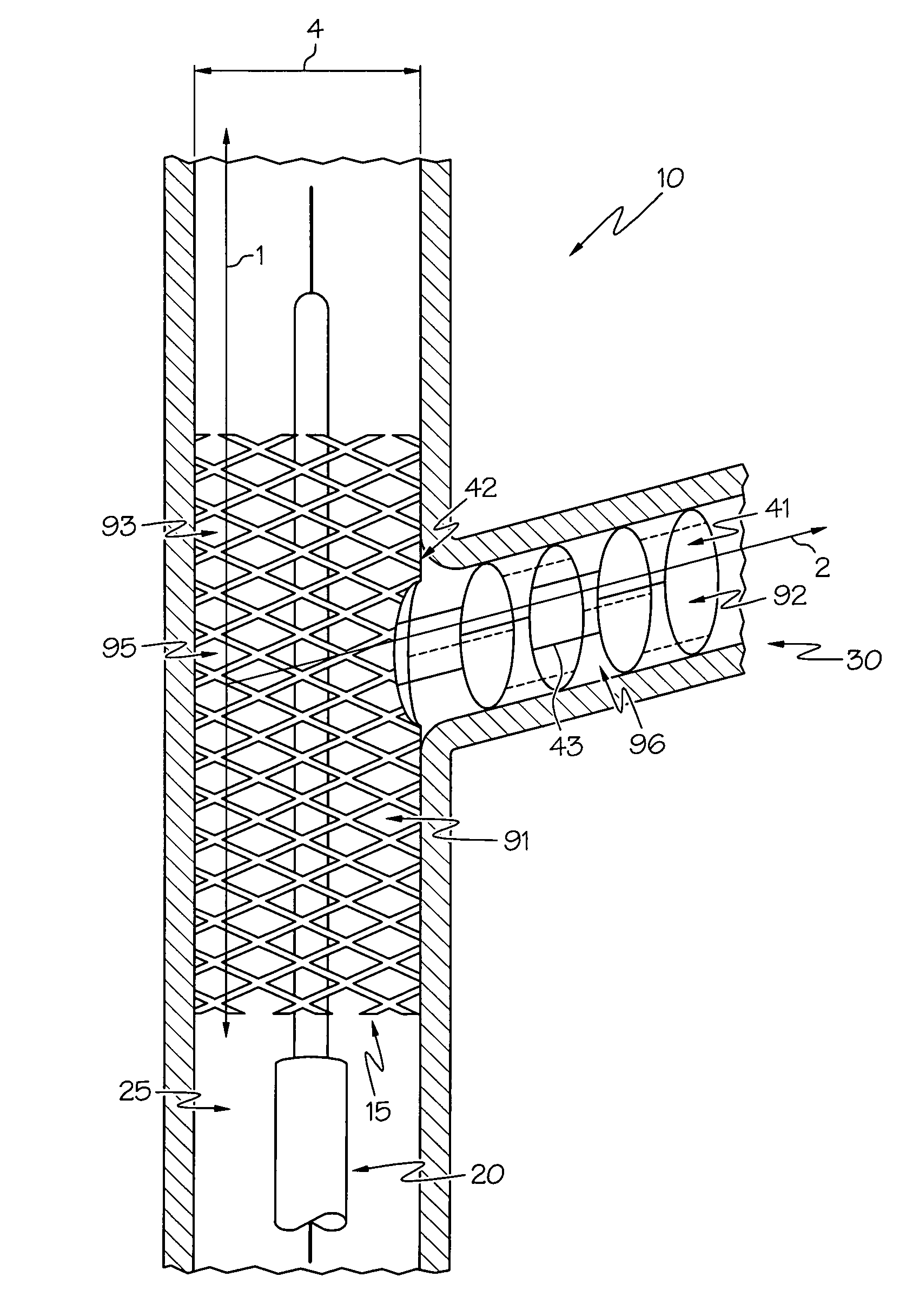
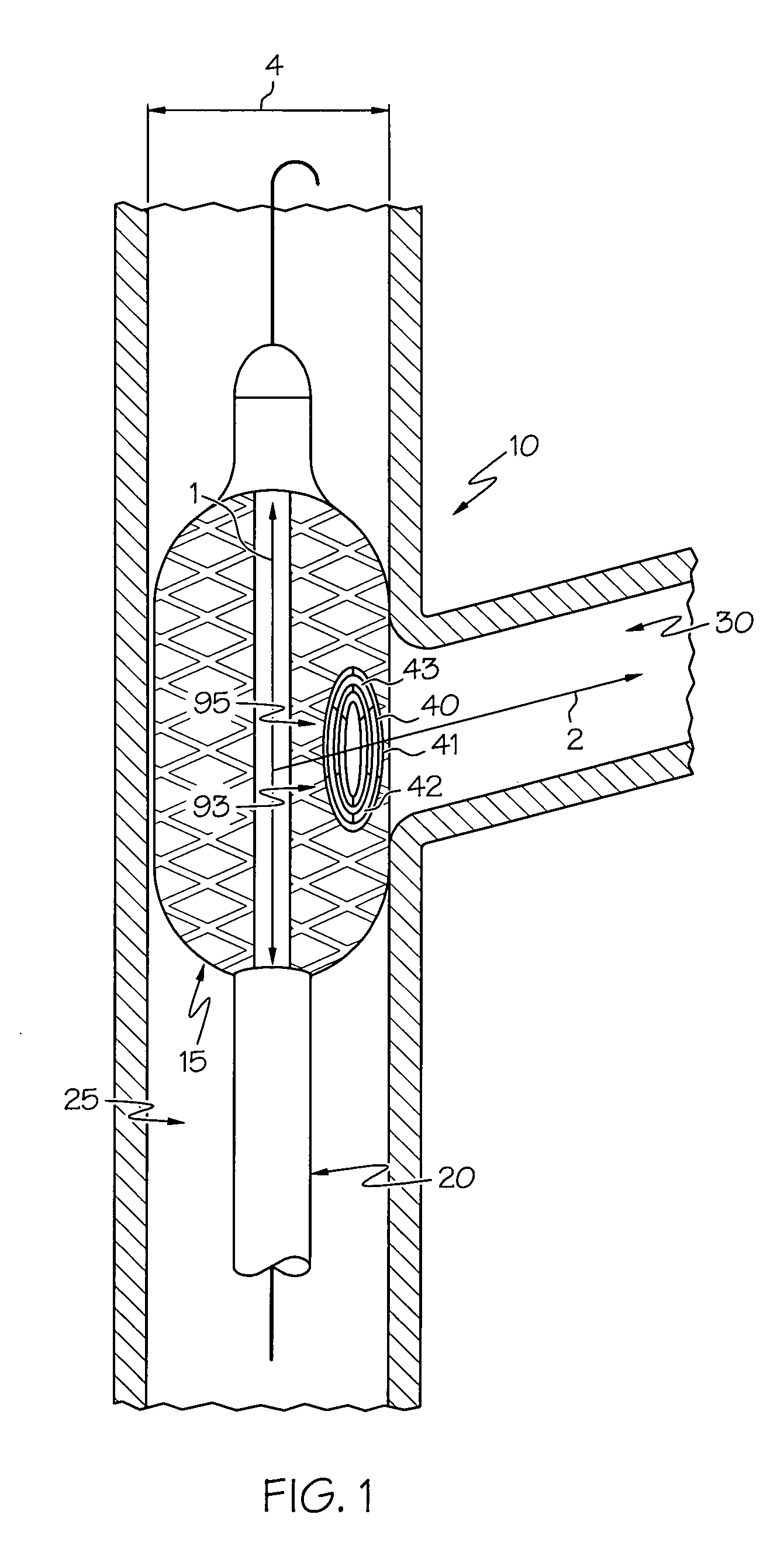
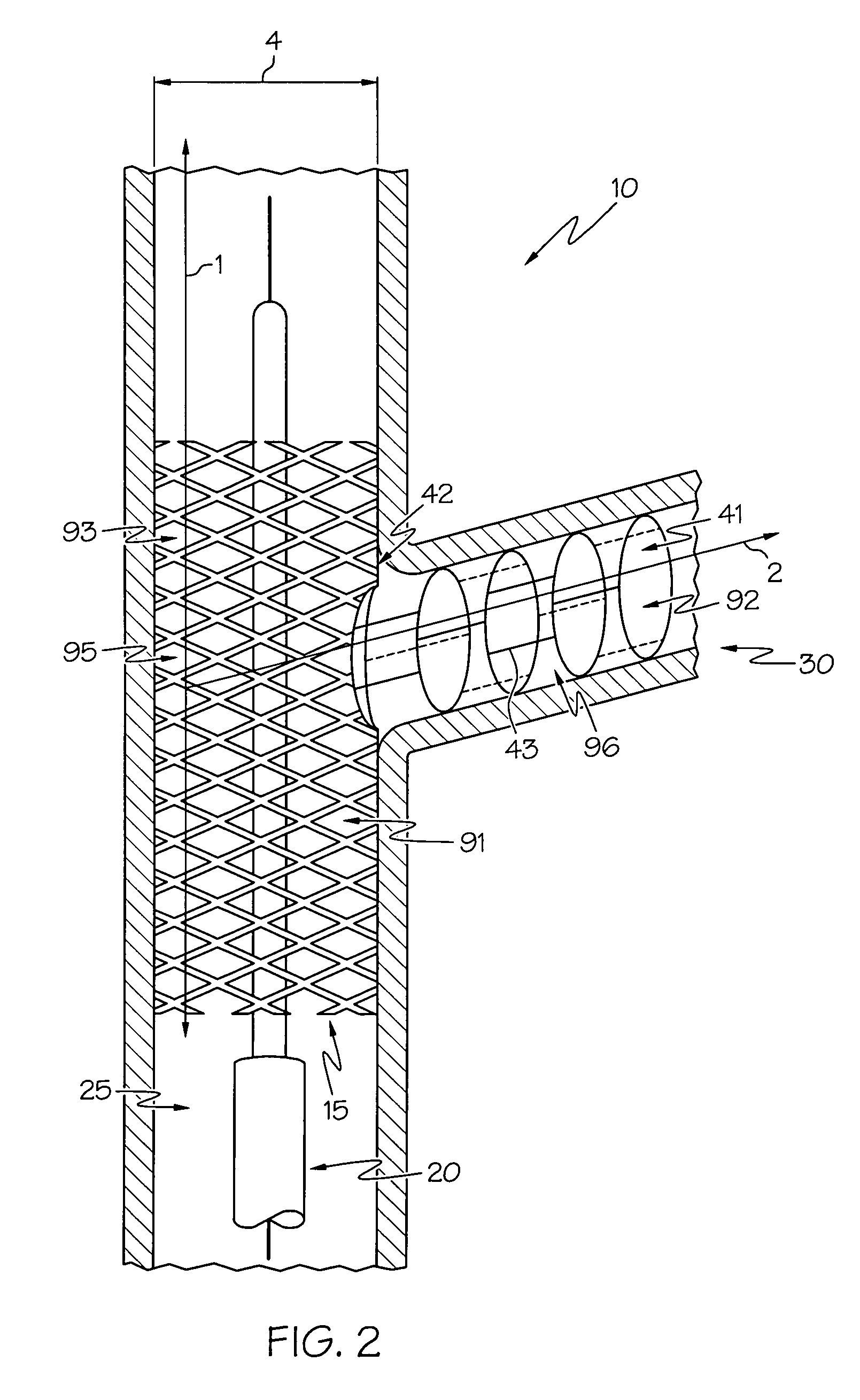
[0066] Referring now to FIG. 1 there is shown an embodiment of the invention featuring an undeployed substantially tubular stent 10 in an unexpanded state placed on a catheter shaft 20 positioned within a body vessel, the body vessel having a first vessel lumen 25 and a second vessel lumen 30 which forms bifurcation from the first vessel lumen 25. The sten...


PUM


Abstract

A bifurcated stent that uses telescoping rings to support or form the side branch lumen. This design allows the bifurcation branch to extend easily, to a useful distance, and to be deployed along oblique angles. Best of all, this design avoids the need to deploy a bent stent.

Description

CROSS-REFERENCE TO RELATED APPLICATIONS [0001] Not Applicable STATEMENT REGARDING FEDERALLY SPONSORED RESEARCH [0002] Not Applicable BACKGROUND OF THE INVENTION [0003] 1. Field of the Invention [0004] In some embodiments this invention relates to implantable medical devices, their manufacture, and methods of use. Some embodiments are directed to delivery systems, such as catheter systems of all types, which are utilized in the delivery of such devices. [0005] 2. Description of the Related Art [0006] A stent is a medical device introduced to a body lumen and is well known in the art. Typically, a stent is implanted in a blood vessel at the site of a stenosis or aneurysm endoluminally, i.e. by so-called “minimally invasive techniques” in which the stent in a radially reduced configuration, optionally restrained in a radially compressed configuration by a sheath and / or catheter, is delivered by a stent delivery system or “introducer” to the site where it is required. The introducer may...

Claims


Application Information

Patent Timeline
IPC IPC(8): A61F2/06A61F2/82A61F2/86A61F2/92
CPCA61F2/82A61F2/856A61F2/86A61F2/91A61F2/92A61F2/93A61F2/954A61F2002/826A61F2250/001A61F2250/006A61F2250/0065A61F2250/0007
Inventor EIDENSCHINK, TRACEEMEYER, MICHAEL P.HEIDNER, MATTGREGORICH, DANIEL
Owner BOSTON SCI SCIMED INC
Why Eureka
Try Eureka