
Cache memory and control method thereof

Active Publication Date: 2007-06-14
SOCIONEXT INC
View PDF10 Cites 40 Cited by
  • Summary
  • Abstract
  • Description
  • Claims
  • Application Information

AI Technical Summary

Benefits of technology

[0007] The present invention has as an object to provide a cache memory which inhibits the influence of other tasks on the cache memory, brought about by task switching, and which easily secures real processing time for a task.

Problems solved by technology

However, with the aforementioned cache memory of the conventional technology, there is the problem that, with the task switching by the processor, the hit ratio of the cache memory is influenced by other tasks which are not currently being executed.
For example, in the case of switching from the execution of a task A to the execution of a task B in a situation where an instruction sequence (or data) of the task A is stored in the cache memory, the instruction sequence (or data) of the task A inside the cache memory is, evicted due to the execution of the task B. Should the instruction sequence (or data) of the task A be evicted from the cache memory, there is the problem that a cache miss occurs when the task A is executed again.
Particularly, in processes requiring real-timeliness, such as the decoding / encoding of compressed audio data and compressed video data, there is the problem that due to the influence of other tasks following such task switching, the time allocated for a task is reduced by the replacement process in the cache after the task switching, and thus the necessary processing time cannot be secured, and real-timeliness is lost or alternatively, processing time cannot be guaranteed.

Method used


Image

  • Cache memory and control method thereof
  • Cache memory and control method thereof
  • Cache memory and control method thereof

Examples


first embodiment

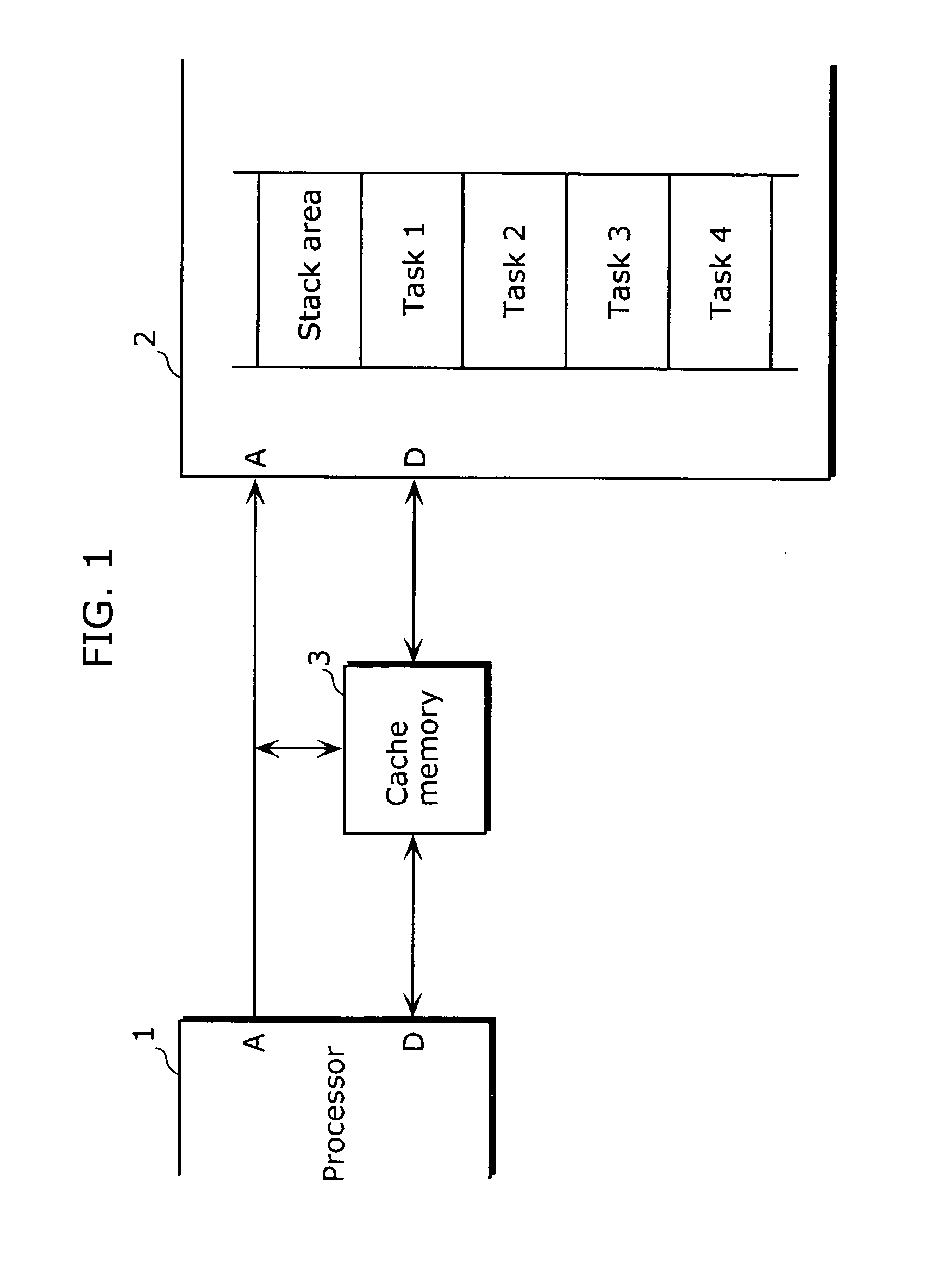
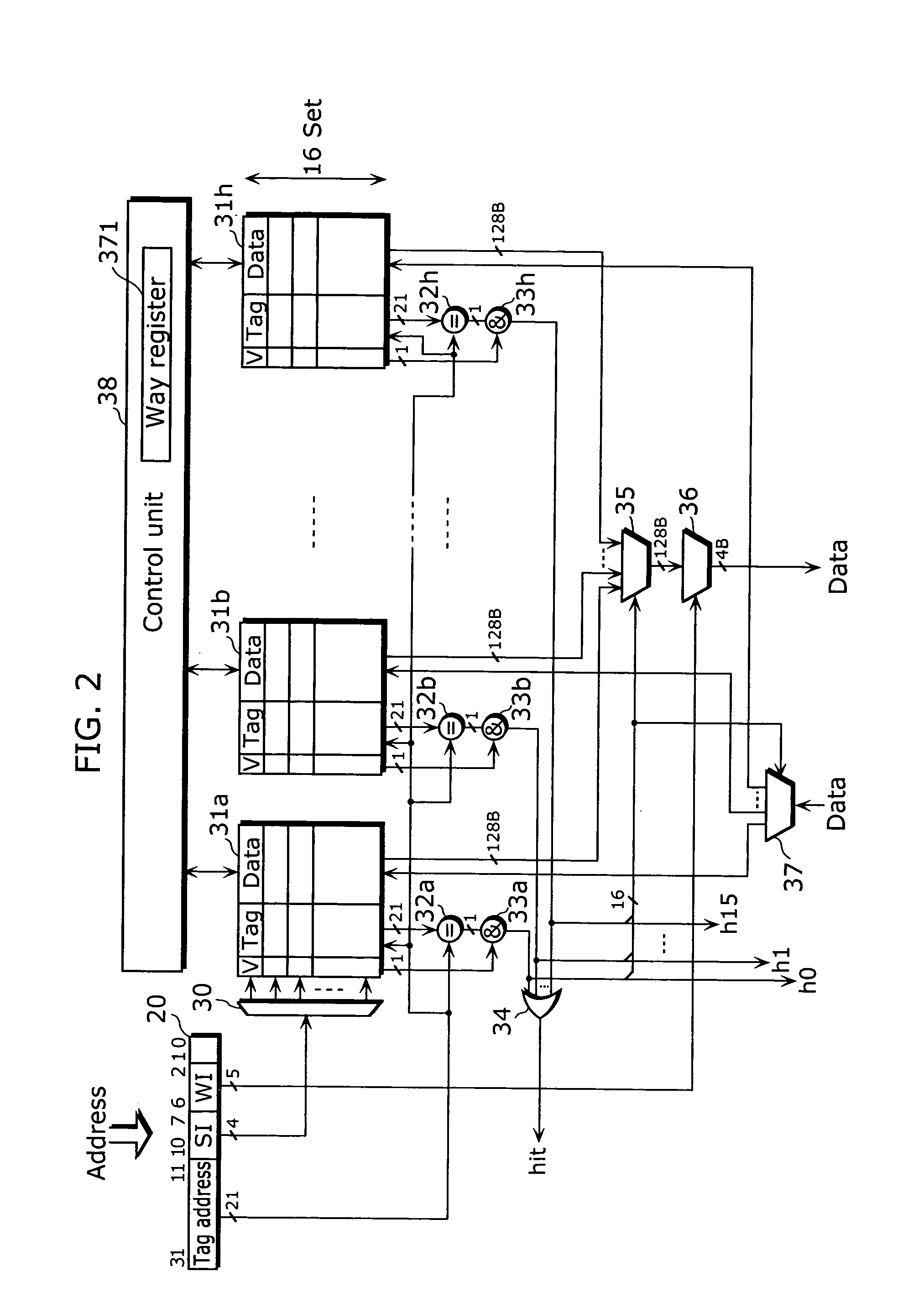
[0064]FIG. 1 is a block diagram showing an outline structure of a system including a processor 1, a cache memory 3, and a memory 2 in the first embodiment of the present invention. In the diagram, the cache memory 3 is included in a system having the processor 1 and the memory 2. The processor 1 is a processor which carries out multi-task control, and which switches and executes tasks 1 to 4 and so on, which are found within the memory 2. The cache memory 3 is an N-way set-associative cache memory which places in a correspondence, one or more ways among N ways, for each of the task, and activates a corresponding way during the execution of a respective task. For the respective tasks, all functions of the cache memory can be used with respect to an active way. Furthermore, for the respective tasks, the functions from among all the functions of the cache memory that can be used is restricted, with respect to a way that is not active (referred to as an inactive way). In the present emb...

second embodiment

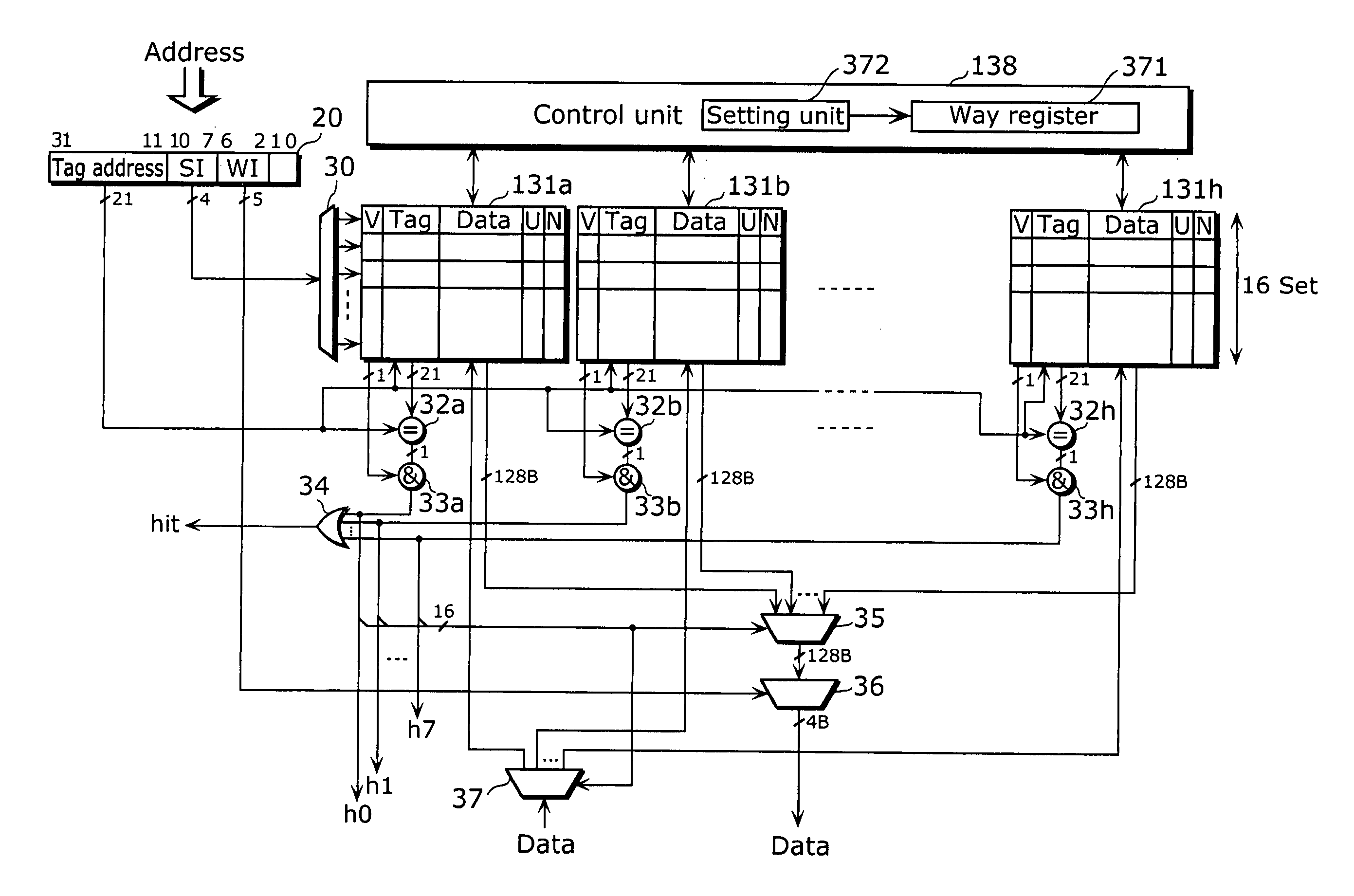
[0101] Although, in the first embodiment, the way register 371 is described as being rewritten due to task switching, the present embodiment describes a structure in which a task is identified in the cash memory, and the way register 371 is rewritten depending on the result of the identification. In addition, although in the first embodiment, the commonly known LRU scheme is adopted as the replacement algorithm, the present embodiment describes a structure which carries out a pseudo-LRU scheme using a 1-bit flag in place of the data indicating the access order.

[0102]FIG. 8 is a block diagram showing the structure of the cache memory in the second embodiment of the present invention. The cache memory in the diagram is different, compared to the structure in FIG. 2, in including ways 131a to 131d in place of the ways 31a to 31d, and including a control unit 138 in place of the control unit 38. Hereinafter, description shall be focused on the points of difference, while omitting the p...

third embodiment

[0141] The first and second embodiments disclose a structure in which the unit of replacement in the cache entry is in line (128 byte) units. The present embodiment describes a structure in which the unit of replacement can be switched between a line unit and a sub-line (32 byte) unit, on a per task basis.

[0142]FIG. 14 is a block diagram showing the structure of the cache memory in the third embodiment of the present invention. The cache memory in the diagram is different, compared to the structure shown in FIG. 8, in including ways 231a to 231h in place of the ways 131a to 131h, the addition of selectors 233a to 233h, and including a control unit 238 in place of the control unit 138. Hereinafter, description shall be focused on the points of difference, while omitting points which are the same.

[0143] The ways 231a to 231h are different, compared to the ways 131a to 131h in FIG. 8, in that instead of holding 1 bit each for the valid flag and the dirty flag within a cache entry, th...


PUM


Abstract

The cache memory in the present invention is an N-way set-associative cache memory including a control register which indicates one or more ways among N ways, a control unit which activates the way indicated by said control register, and an updating unit which updates contents of said control register. The control unit restricts at least replacement, for a way other than the active way indicated by the control register.

Description

TECHNICAL FIELD [0001] The present invention relates to a cache memory and a control method thereof, for facilitating high-speed memory access from a processor. BACKGROUND ART [0002] A cache memory has conventionally been utilized for shortening main memory access time and improving the processing performance of a processor. [0003] For example, a cache memory disclosed in Japanese Laid-Open Patent Application No. 6-266620 Publication stores main memory data, on a block basis, into respective entries, and performs, via such entries, transfer control and exclusive access control for the data corresponding to the access from a processing unit performing multi-task processing. Such cache memory is equipped, for each entry, with a task identification information registration unit which registers the identification information of each task of a processing unit, which is set as the subject of the exclusive access control for the block stored in the entry, and performs, on a task basis, exc...

Claims


Application Information

Patent Timeline
IPC IPC(8): G06F12/00G06F12/12
CPCG06F12/0842G06F12/0848G06F12/121G06F12/126G06F12/12
Inventor TANAKA, TETSUYA
Owner SOCIONEXT INC
Learn More