Method and system for testing backplanes utilizing a boundary scan protocol

a backplane and boundary scan technology, applied in the field of methods and systems for testing backplanes utilizing boundary scan protocols, can solve the problems of increasing increasing the difficulty of use, and increasing the complexity of the bed of nails test device, so as to increase the complexity and overall size of the backplane configuration

Inactive Publication Date: 2007-06-14
TELLABS OPERATIONS
View PDF14 Cites 14 Cited by
  • Summary
  • Abstract
  • Description
  • Claims
  • Application Information

AI Technical Summary

Benefits of technology

[0005] In the past, connectivity testing has been performed utilizing a “bed of nails” test device. The bed of nails test device grows in complex and becomes more difficult to use as the complexity and ov

Problems solved by technology

The bed of nails test device grows in complex and becomes more difficult to use as the complexity and over

Method used


Image

  • Method and system for testing backplanes utilizing a boundary scan protocol
  • Method and system for testing backplanes utilizing a boundary scan protocol
  • Method and system for testing backplanes utilizing a boundary scan protocol

Examples


Embodiment Construction

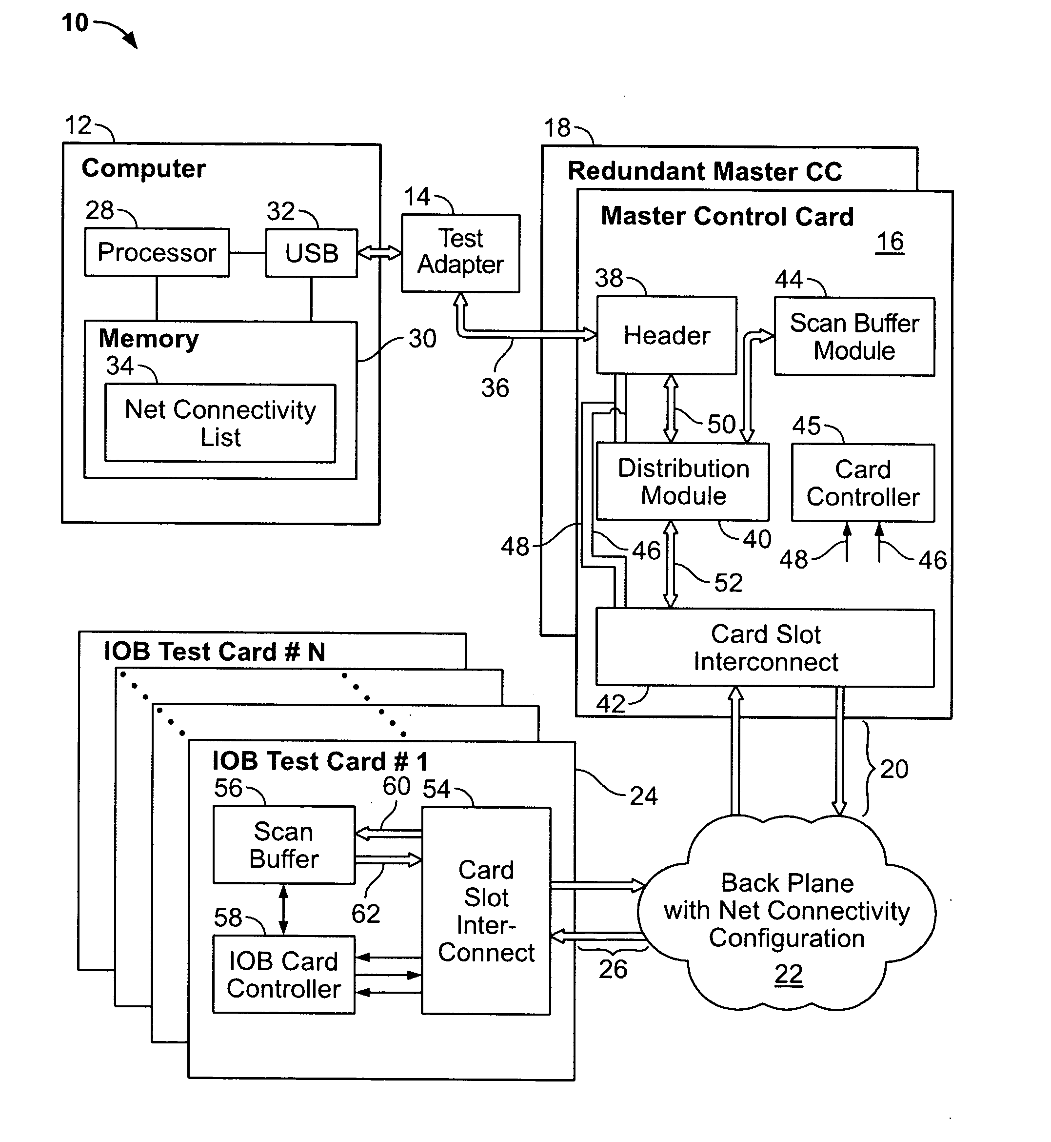
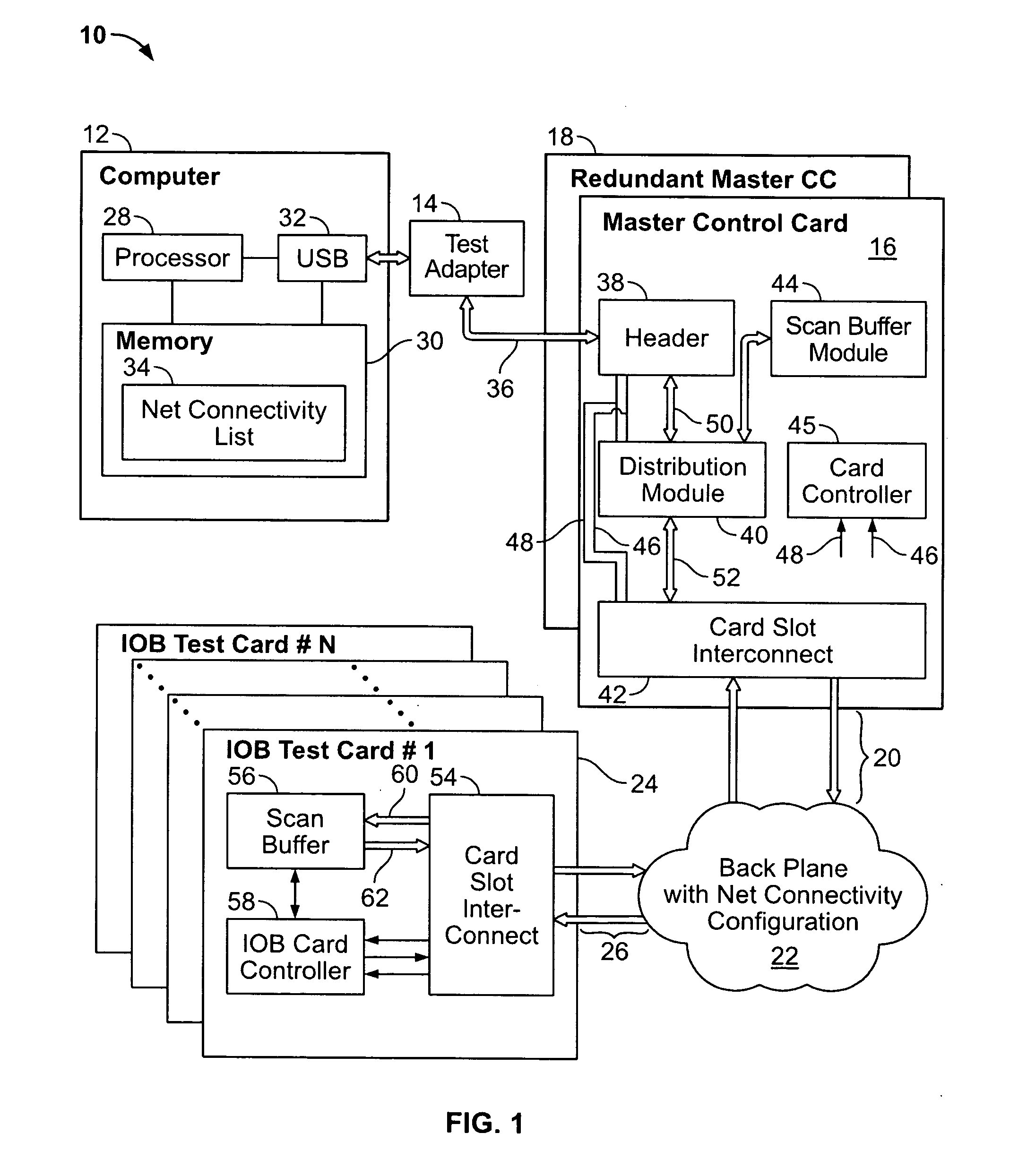
[0015]FIG. 1 illustrates a block diagram of a connectivity test system 10 that is provided in accordance with an embodiment of the present invention. The system 10 includes a computer 12 that is joined through a test adapter 14 to one or more master control cards 16. In the example of FIG. 1, a redundant master control card 18 is illustrated, but is not necessary. The master control card 16 is joined at card slot interface 20 to a backplane 22. The backplane 22 includes a series of card slots, each of which includes a series of nets (e.g., contact pins or contact receptacles) interconnected with nets in the same and / or different card slots. The system 10 also includes a series of input / output board (IOB) test cards 24 that are joined to the backplane 22 over card slot interfaces 26. Each IOB test card 24 is constructed similarly and thus only one will be described in detail hereafter.

[0016] The computer 12 includes, among other things, a processor module 28, memory 30, and a USB po...


PUM


Abstract

A system is provided for testing connectivity of a backplane having card slots with multiple nets in each card slot. The system includes a processor module that generates test vectors based on a net connectivity configuration for a predetermined backplane architecture. A master control card includes a card slot interconnect that is configured to be plugged into nets in the backplane. The master control card communicates over a serial interface with the processor module. The master control card receives the test vectors, associated with multiple card slots, over the serial interface. The master control card is configured to test the connectivity of the backplane based on the test vectors. Optionally, IOB test cards may be included that each have a card slot interconnect that is configured to be plugged into nets in a respective card slot of the backplane. The IOB test cards are joined in series with the master control card and with one another. Optionally, the test vectors may be defined based on an IEEE 1149.1 boundary scan test protocol.

Description

RELATED APPLICATION [0001] The present application relates to and claims priority from Provisional Application Ser. No. 60 / 738,348, filed Nov. 19, 2005, titled “METHOD AND SYSTEM FOR TESTING BACKPLANES UTILIZING A BOUNDARY SCAN PROTOCOL”, the complete subject matter of which is hereby expressly incorporated by reference in its entirety.BACKGROUND OF THE INVENTION [0002] The present invention generally relates to methods and systems for testing backplanes utilizing a boundary scan protocol. [0003] Backplanes are utilized in a variety of communications and data transfer applications. A backplane is typically provided in a chassis organized into card slots, each of which is configured to receive processor modules, port modules and the like. Each card slot includes at least one interface configured to join with a module inserted therein. The interface includes a configuration of contact receptacles or contact pins (generally referred to as nets). Each module includes a card slot interco...

Claims


Application Information

Patent Timeline
IPC IPC(8): G01R31/28G06F11/00
CPCG01R31/318508G01R31/318536
Inventor GOVANI, ATUL V.TALEN, GERALD A.
Owner TELLABS OPERATIONS
Why Eureka
Try Eureka