Fast-moving screw assembly

Inactive Publication Date: 2007-06-21
BOSCH REXROTH MECHATRONICS
View PDF5 Cites 5 Cited by
  • Summary
  • Abstract
  • Description
  • Claims
  • Application Information

AI Technical Summary

Benefits of technology

[0024] However, it may also be provided that the allocation means include a table, which associates a spindle rpm with individual predetermined nut positions, and calculation means, which linearly interpolate the spindle rpm between the predetermined nut positions. This embodiment has the advantage that it is easy to perform using universal machine controllers, since complicated calculations do not have to be made.
[0025] Moreover, a memory-programmable controller may be provided, which has a drive command that drives the nut with the aid of the allocation means. For instance, in a known controller of a machine tool, a rapid-feed command may be provided, which in accordance with the method of the invention moves a machine sled that is driven by a screw assembly. A rapid-feed command typically has the task of moving the machine sled from its current position to a target position as fast a

Problems solved by technology

Particularly with long spindles, this rpm is very low

Method used


Image

  • Fast-moving screw assembly
  • Fast-moving screw assembly
  • Fast-moving screw assembly

Examples


Example

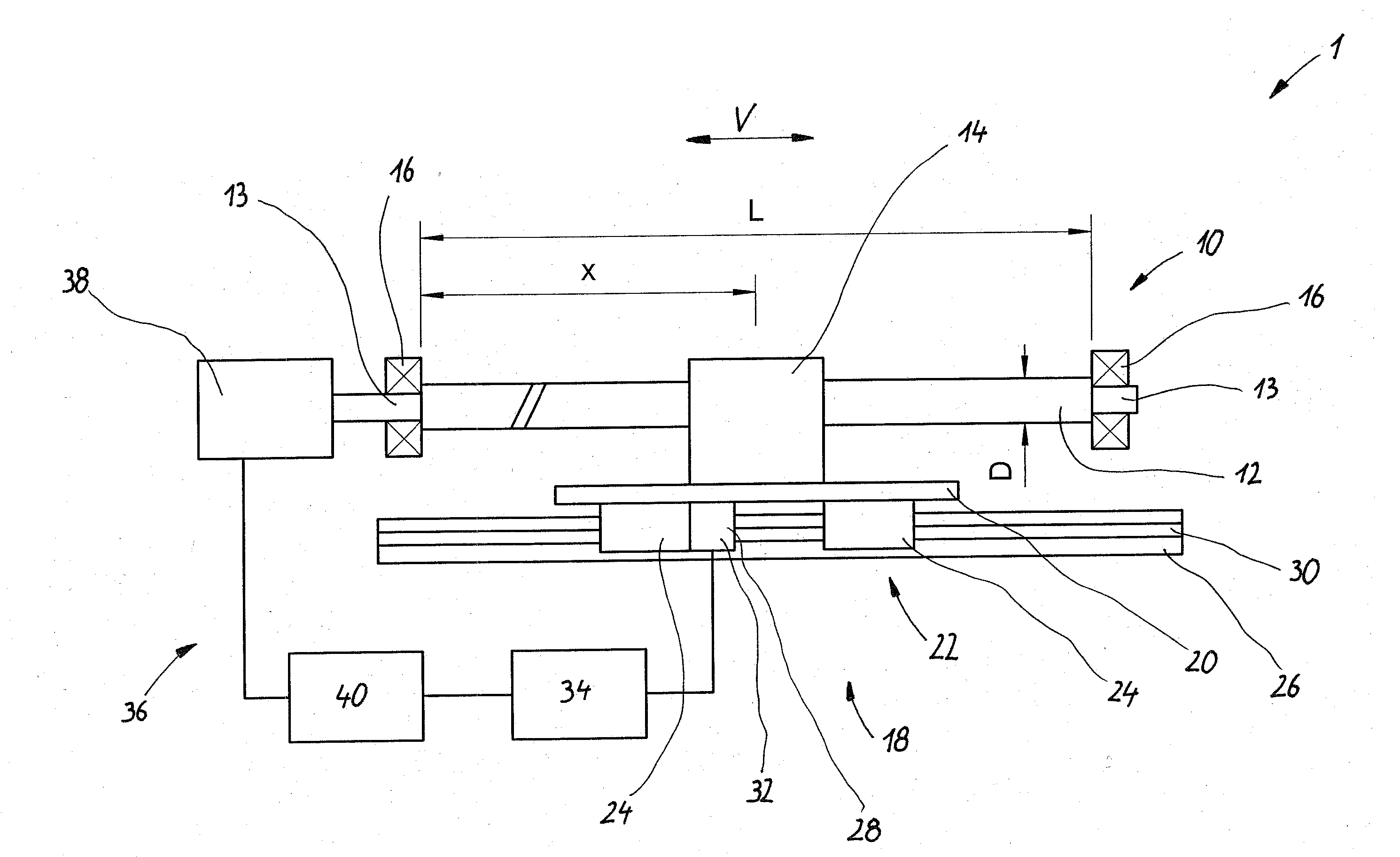
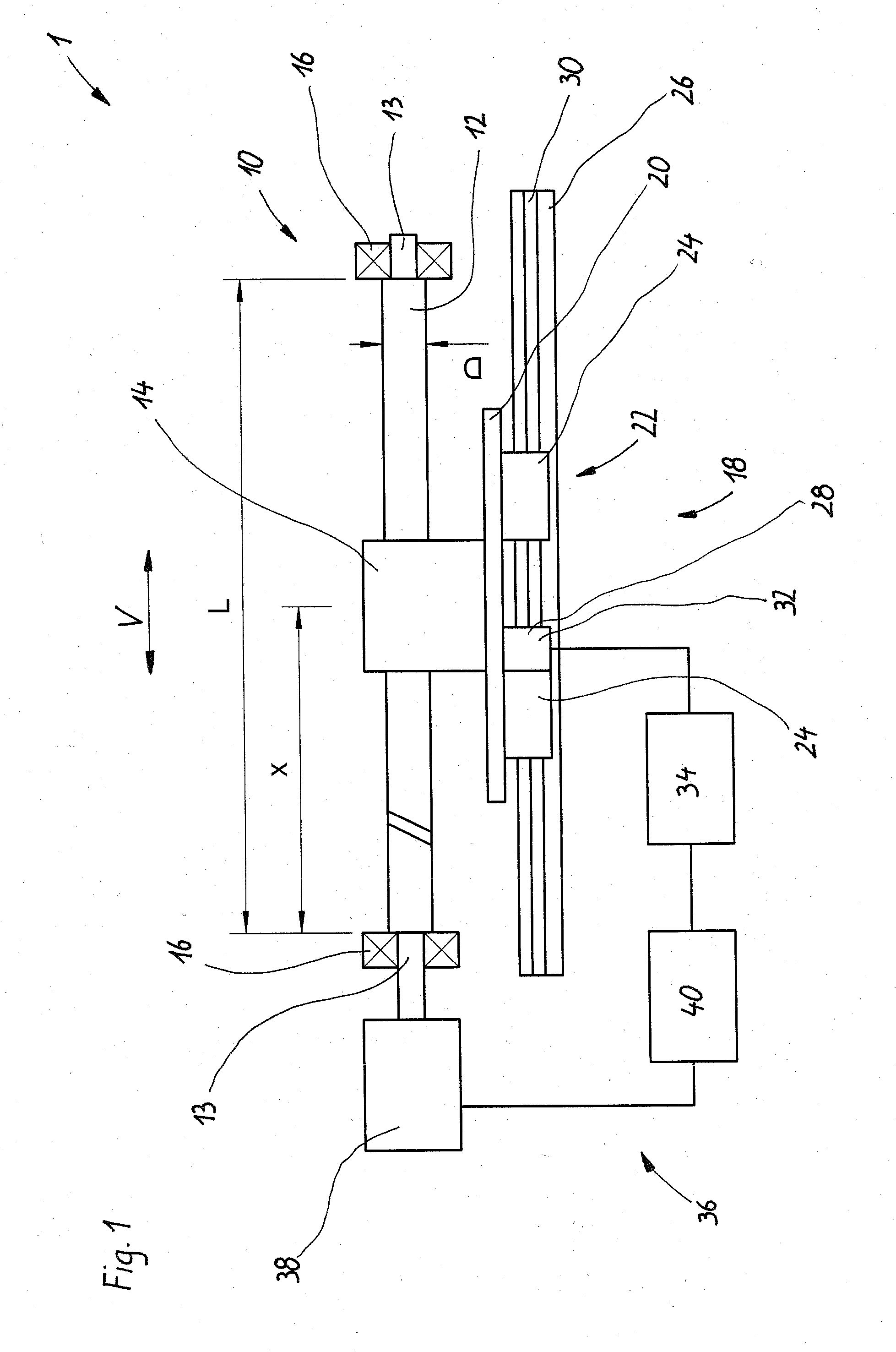
[0030] In FIG. 1, an apparatus according to the invention, having a screw assembly 10, is identified overall by reference numeral 1. The screw assembly 10, whose forward- feed direction is marked V, includes a spindle 12 and a nut 14. The screw assembly 10 is a ball screw assembly with clockwise motion, having the following specifications: Spindle diameter (D):50mmPitch:40mmBall diameter:6.5mmSpindle length (L):5000mmPrestressing category:3% of the dynamic load-bearing coefficient

[0031] The spindle is rotatably supported on both ends 13 by means of bearings 16, namely radial-fluted ball bearings. The two bearings 16 are embodied as fixed bearings; that is, neither of the two bearings 16 allows any motion of the spindle ends 13 in the forward-feed direction V.

[0032] The nut 14 is braced transversely to the forward-feed direction V on a primary subassembly 18 formed by a table 20, which is supported on a linear roller bearing 22 so as to be movable in the forward-feed direction V. T...


PUM


Abstract

In a method for operating a screw assembly, having a spindle, which is rotatably supported on at least one end, and a nut, which is drivable by the spindle in a forward-feed direction, the nut being braced transversely to the forward-feed direction on a primary subassembly, and the spindle rpm is selected as a function of the position of the nut such that this rpm is just below a position-dependent limit rpm, in order to attain the shortest possible travel time.

Description

CROSS-REFERENCE TO A RELATED APPLIACTION [0001] The invention described and claimed hereinbelow is also described in German Patent Application DE 10 2005 054 290.5 filed on Nov. 11, 2005. This German Patent Application, whose subject matter is incorporated here by reference, provides the basis for a claim of priority of invention under 35 U.S.C. 119(a)-(d). BACKGROUND OF THE INVENTION [0002] The invention relates to a method for operating a screw assembly and to an apparatus for performing the method. [0003] One such method is known for instance from German Patent Disclosure DE 198 21 763 A1. In this reference, the problems of the bending-critical rotary rpm, namely if the effect that the screw assembly on reaching this rpm experiences bending oscillations by which it can be damaged or destroyed, is described in conjunction with FIG. 12. The bending-critical rpm is fundamentally dependent on the unbraced length of a rotating shaft. In a screw assembly in which the nut is braced tran...

Claims


Application Information

Patent Timeline
IPC IPC(8): F16H27/02
CPCF16H25/20Y10T74/18576F16H25/2204
Inventor KLEIN, MICHAELGREUBEL, ROLAND
Owner BOSCH REXROTH MECHATRONICS
Why Eureka
Try Eureka