Thermoelectric tunnelling device

a tunnelling device and tunnelling technology, applied in the direction of thermoelectric devices with peltier/seeback effect, electrical equipment, electric discharge tubes, etc., can solve the problems of high operating temperature, high manufacturing cost, and high operating temperature of vacuum gap designs, and achieve the effect of requiring a very small gap for operation

Inactive Publication Date: 2007-06-21
THE BOEING CO
View PDF3 Cites 44 Cited by
  • Summary
  • Abstract
  • Description
  • Claims
  • Application Information

AI Technical Summary

Problems solved by technology

These early vacuum gap designs have high manufacturing costs and high operating temperatures-above 1000

Method used


Image

  • Thermoelectric tunnelling device
  • Thermoelectric tunnelling device
  • Thermoelectric tunnelling device

Examples


Embodiment Construction

[0018] In the following description, reference is made to the accompanying drawings which form a part hereof, and which is shown, by way of illustration, several embodiments of the present invention. It is understood that other embodiments may be utilized and structural changes may be made without departing from the scope of the present invention.

Overview

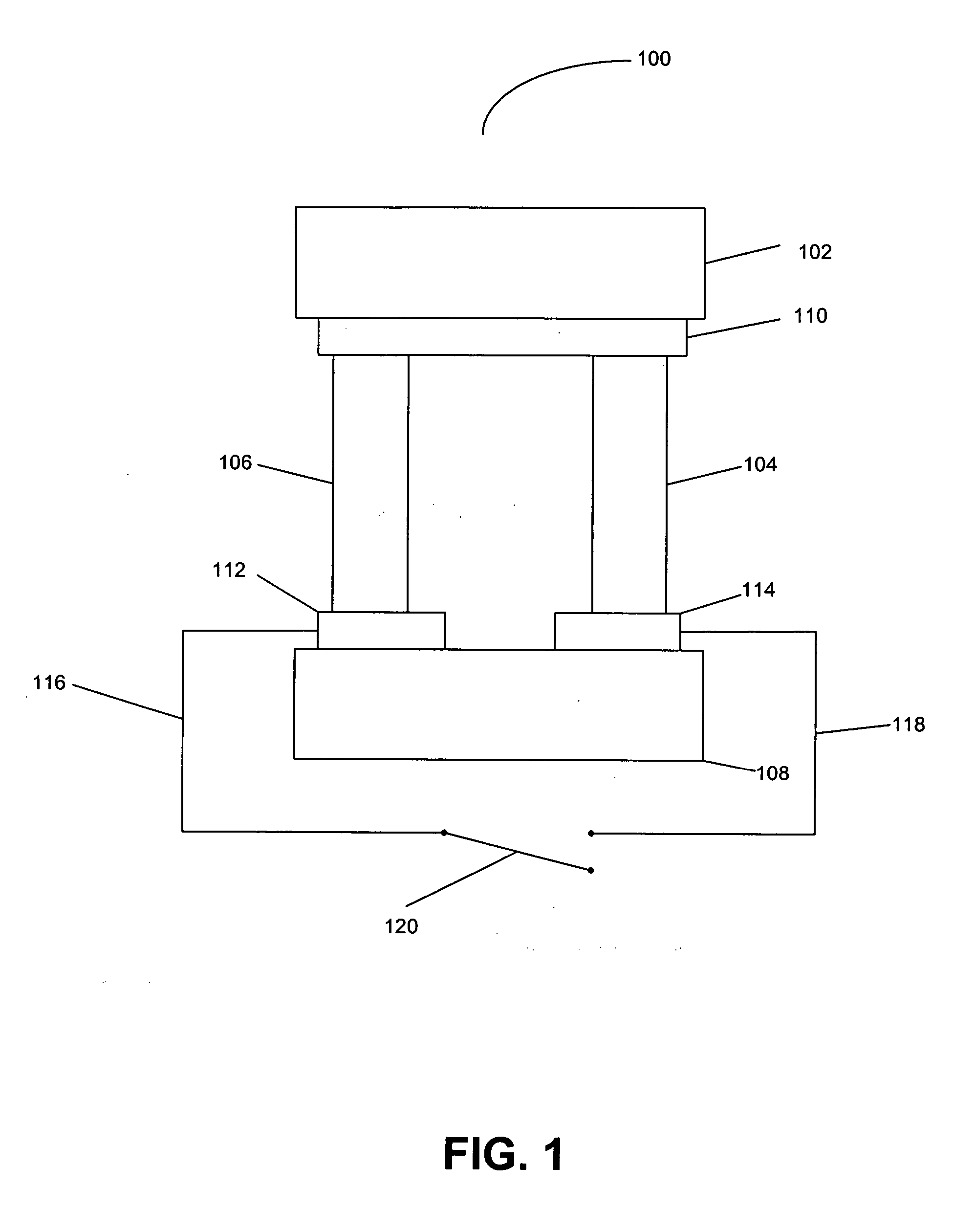
[0019]FIG. 1 is a cross-sectional view of a solid state thermal engine according to the related art.

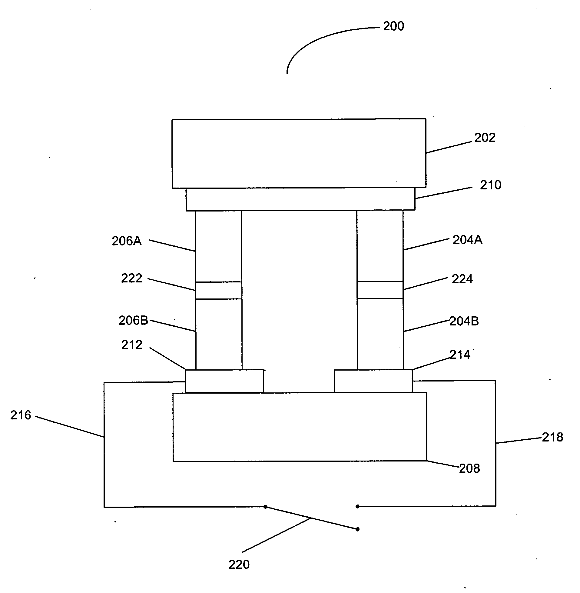
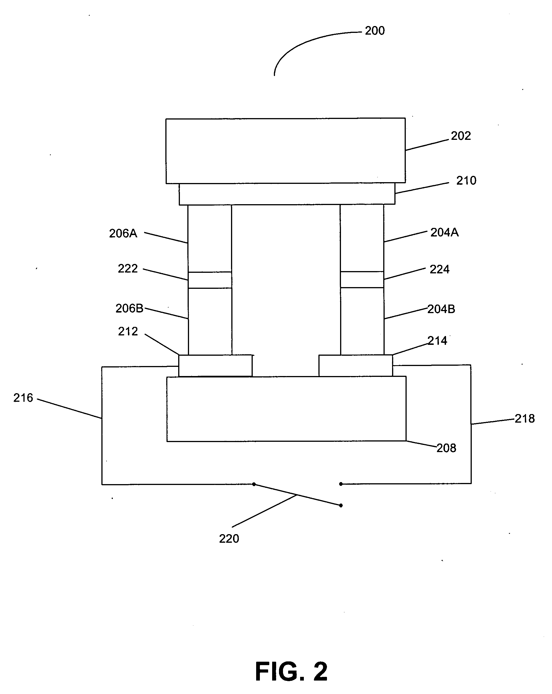
[0020] Device 100 comprises a hot electrode 102, an n-type column 104, a p-type column 106, a cold electrode 108, an ohmic contact 110 between hot electrode 102 and both columns 104 and 106, an ohmic contact 112 between p-type column 106 and cold electrode 108, and an ohmic contact 114 between n-type column 104 and cold electrode 108. Conductor 116 is coupled to contact 112, conductor 118 is coupled to contact 114, and switch 120 is also provided, to allow for a load to be connected across the device 100.

[0021] In device 100, the...


PUM


Abstract

Methods and apparatuses for making a thermotunneling device. A method in accordance with the present invention comprises metal/semiconductor or semiconductor/semiconductor bonded material combinations that allows current flow between a hot plate and a cold plate of a thermoelectric device, and interrupting a flow of phonons between the hot plate and the cold plate of the thermoelectric device, wherein the interrupted flow is caused by a nanogap, said nanogap being formed by applying a small voltage or current between the two sides of the thermoelectric device.

Description

BACKGROUND OF THE INVENTION [0001] 1. Field of the Invention [0002] The present invention relates generally to electrical power generation and, more specifically, to direct thermal-to-electric energy conversion power generating systems. [0003] 2. Description of the Related Art [0004] Solid state thermal engines are devices that perform direct thermal-to-electric energy conversion without any moving parts. The solid state thermal engine is driven by hot sources, such as engine bleed air, wasted heat from operation of an electromechanical or thermal system, or some other heat source, such as the sun. [0005] Solid state thermal engine technology is based on thermionics. Thermionics originated nearly a century ago with a basic vacuum tube, a device that consisted of two parallel conductive plates (a high temperature cathode and a low temperature anode) separated by a vacuum gap. During operation electrons boil off the cathode, traverse the gap and then are absorbed into the colder anode...

Claims


Application Information

Patent Timeline
IPC IPC(8): H01L35/30
CPCH01J45/00H01L35/00H10N10/00
Inventor TANIELIAN, MINAS H.
Owner THE BOEING CO
Why Eureka
Try Eureka