Thermal transfer technique using heat pipes with integral rack rails

a heat pipe and rack rail technology, applied in the direction of tubular elements, lighting and heating apparatus, cooling/ventilation/heating modifications, etc., can solve the problems of inability to store valuable data, prohibitive restorative expenditure, and heat generation by electronic components used,

Active Publication Date: 2009-12-01
ORACLE INT CORP
View PDF13 Cites 62 Cited by
  • Summary
  • Abstract
  • Description
  • Claims
  • Application Information

AI Technical Summary

Problems solved by technology

Heat generation by electronic components used, for example, in computer systems is a major issue of concern to industry.
The shrinking of electronic circuit sizes with increasing speed of processors has further lead to circuits having to be stacked one above the other with little space therebetween.
When space constraints and inefficient thermal cooling systems cause the heat density to rise above a tolerance limit in stacked circuits of computing systems, failure of components could occur resulting in loss of valuable data and prohibitive restorative expenditures.

Method used


Image

  • Thermal transfer technique using heat pipes with integral rack rails
  • Thermal transfer technique using heat pipes with integral rack rails
  • Thermal transfer technique using heat pipes with integral rack rails

Examples


Embodiment Construction

[0017]Various exemplary embodiments of the invention will now be described with reference to the accompanying figures. Like elements are referred to by like reference numerals in the several views for the sake of clarity.

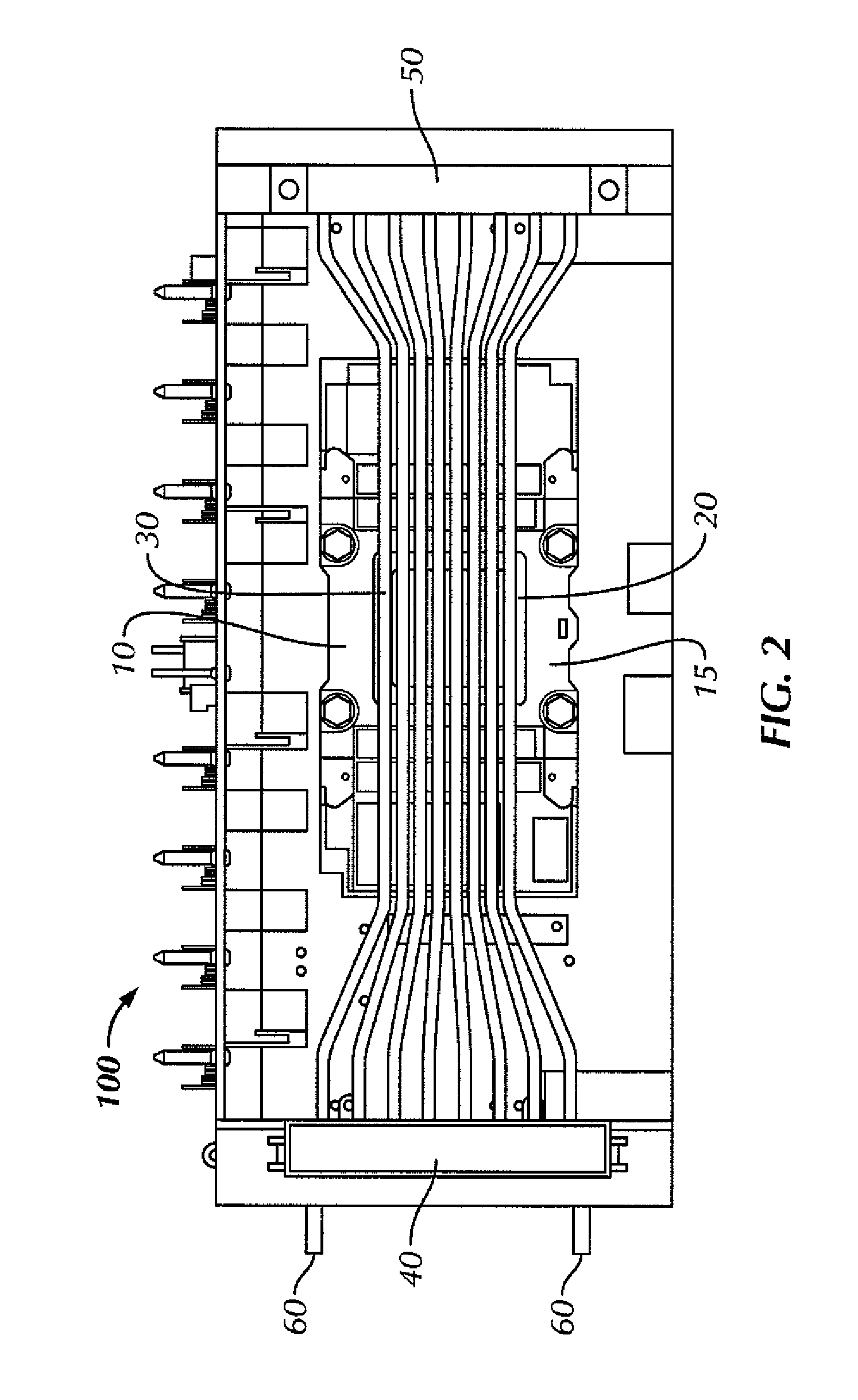
[0018]Referring to FIG. 2, in accordance with one or more embodiments of the invention, a thermal transfer apparatus 100 comprises of an evaporator 10 with a source cold plate 15 disposed over a heat-producing electronic circuit 20 and thermally coupled thereof. An array of heat pipes 30 carrying a working fluid inside is disposed over the evaporator 10 and thermally coupled thereto. The heat pipes 30 extend from an end comprising a cold plate 40 to an end comprising a condenser 50 over the evaporator 10, and the coolant supply lines 60 to the cold plate 40 and the condenser 50 are outside the thermal transfer apparatus 100. Because of this, leakage of coolant inside the apparatus is prevented.

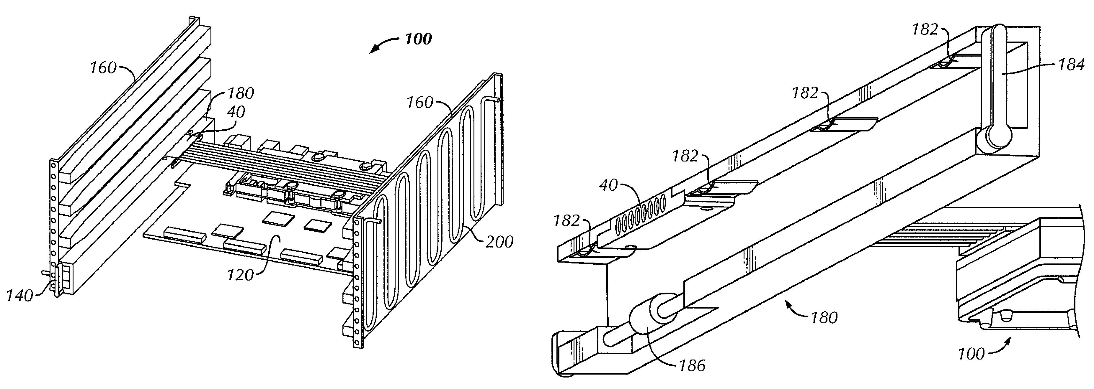
[0019]FIG. 3 shows the thermal transfer apparatus 100 as part of a tray 1...


PUM


Abstract

A thermal transfer apparatus for cooling a heat-producing electronic component includes an evaporator disposed over the heat-producing electronic component and thermally coupled to the heat-producing electronic component, a plurality of heat pipes carrying a working fluid therein disposed over the evaporator and thermally coupled to the evaporator, a cold plate thermally coupled to a first end of the plurality of heat pipes, and a condenser thermally coupled to a second end of the plurality of heat pipes. The heat pipes extend over the evaporator such that the first end and the second end of the heat pipes couple to the cold plate and condenser at a location not over the heat-producing electronic component. The cold plate and the condenser are supplied with a coolant from outside the thermal transfer apparatus.

Description

BACKGROUND OF INVENTION[0001]Heat generation by electronic components used, for example, in computer systems is a major issue of concern to industry. Reliability of electronic components such as semiconductor chips being a function of temperature necessitates removal of the generated heat from the electronic components with the aid of external means. The shrinking of electronic circuit sizes with increasing speed of processors has further lead to circuits having to be stacked one above the other with little space therebetween.[0002]When space constraints and inefficient thermal cooling systems cause the heat density to rise above a tolerance limit in stacked circuits of computing systems, failure of components could occur resulting in loss of valuable data and prohibitive restorative expenditures. Thus, efficient and compact design of the external devices for evacuating heat away from the electronics is necessary.[0003]Typical solutions involving heat pipes, as shown in Prior Art FI...

Claims


Application Information

Patent Timeline
Patent Type & Authority Patents(United States)
IPC IPC(8): H05K7/20F28F1/00
CPCH05K7/20672F28D15/0266
Inventor KONSHAK, MICHAEL V.XU, GUOPINGANESHANSLEY, NICHOLAS E.
Owner ORACLE INT CORP
Why Eureka
Try Eureka