

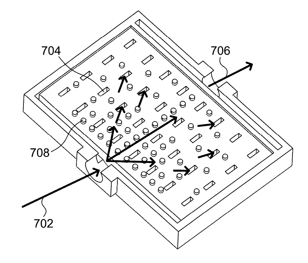
Micro Heat Transfer Arrays, Micro Cold Plates, and Thermal Management Systems for Cooling Semiconductor Devices, and Methods for Using and Making Such Arrays, Plates, and Systems
a technology of heat transfer arrays and cold plates, which is applied in the direction of electrical apparatus construction details, lighting and heating apparatuses, laminated elements, etc., can solve the problems of destroying the separation of masking materials from the substrate, and achieve the effect of high surface area
- Summary
- Abstract
- Description
- Claims
- Application Information
AI Technical Summary
Benefits of technology
Problems solved by technology
Method used
Image

Examples
Embodiment Construction
[0125]Electrochemical Fabrication in General
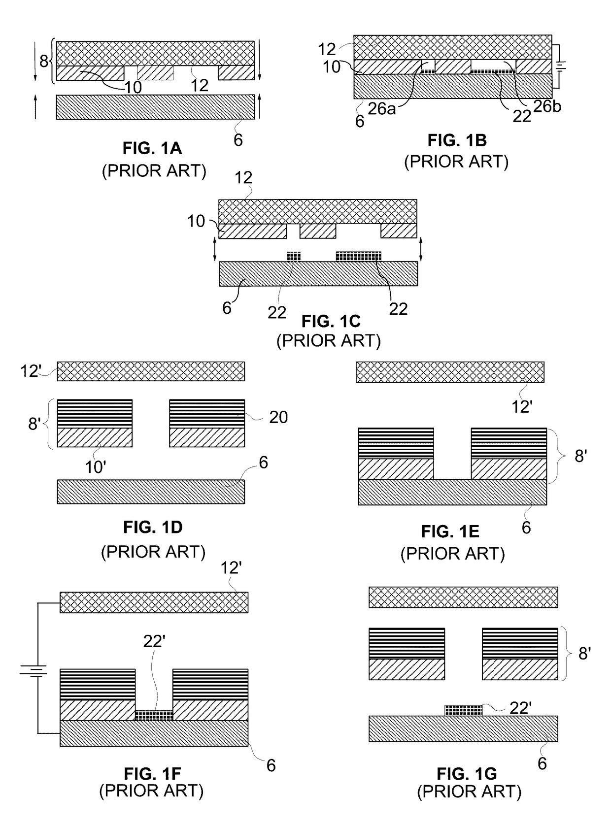
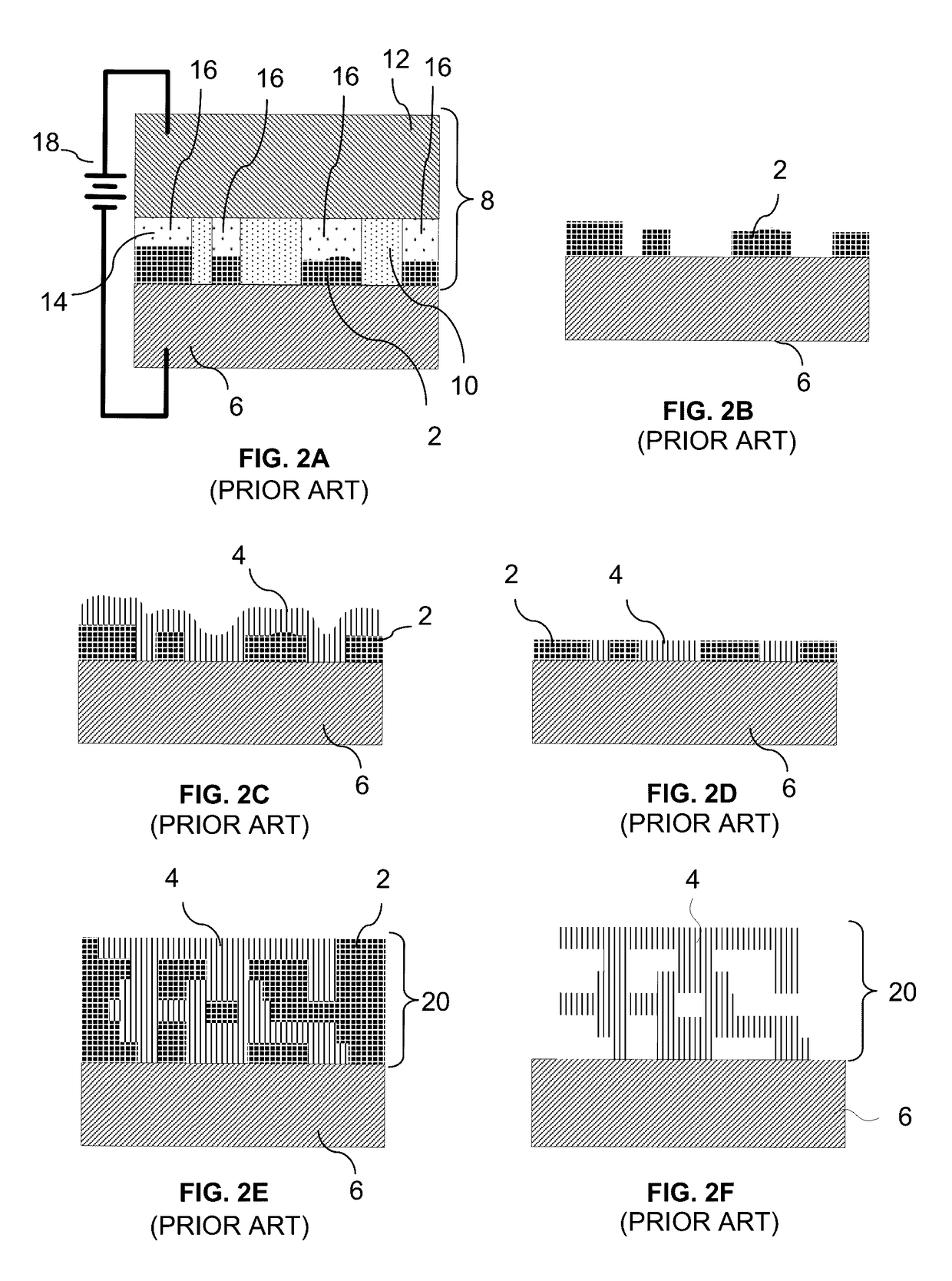
[0126]FIGS. 1A-1G, 2A-2F, and 3A-3C illustrate various features of one form of electrochemical fabrication. Other electrochemical fabrication techniques are set forth in the '630 patent referenced above, in the various previously incorporated publications, in various other patents and patent applications incorporated herein by reference. Still others may be derived from combinations of various approaches described in these publications, patents, and applications, or are otherwise known or ascertainable by those of skill in the art from the teachings set forth herein. All of these techniques may be combined with those of the various other embodiments or various aspects of the invention to yield enhanced embodiments. Still other embodiments may be derived from mixing and matching elements and steps into new combinations based on the various embodiments explicitly set forth herein.
[0127]FIGS. 4A-4I illustrate side views of various states in a...
PUM
 Abstract
Description
Claims
Application Information