Milling arrangement for tunnel walls

a technology for tunnel walls and milling arrangements, applied in the direction of tunnel linings, cutting machines, stone-like material working apparatuses, etc., can solve the problems of carbon black layer and concrete starting to bum

Inactive Publication Date: 2007-06-21
BLASTRAC
View PDF9 Cites 13 Cited by
  • Summary
  • Abstract
  • Description
  • Claims
  • Application Information

AI Technical Summary

Benefits of technology

[0007] In a further preferred embodiment the milling device is tiltable around two orthogonal axes which extend orthogonally with respect to the first direction. The fact that the milling device is tiltable allows for the cutting tool to follow closely the shape of the tunnel wall, such that a uniform grinding of the surface is achieved.
[0008] In an especially preferred embodiment the guide comprises two parallel guiding tracks each comprising a pair of spaced apart parallel cylindrical members, wherein the space between the cylindrical members is such that a guiding roll can move between them while engaging both cylindrical members. This allows for a tilting movement of the guiding roll between the cylindrical guiding members and thus a tilting of the milling device. The guiding rolls are rotatably mounted on the casing of the milling device such that also a tilting movement around the axis of the rolls of the milling device is possible.

Problems solved by technology

In case of a fire in the tunnel the carbon black layer as well as the concrete can start to bum due to very high temperatures which typically occur in case of tunnel fires.

Method used


Image

  • Milling arrangement for tunnel walls
  • Milling arrangement for tunnel walls
  • Milling arrangement for tunnel walls

Examples


Embodiment Construction

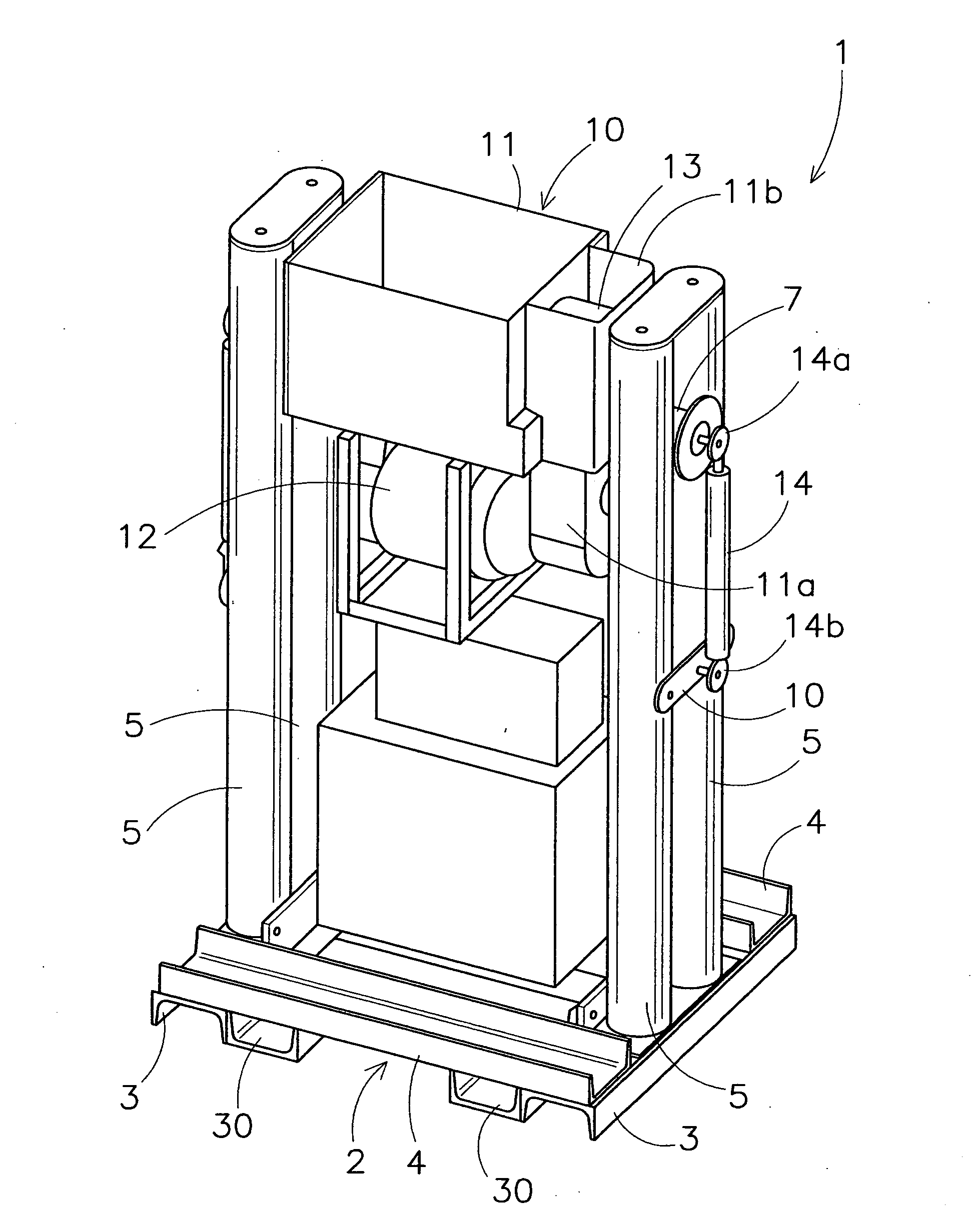
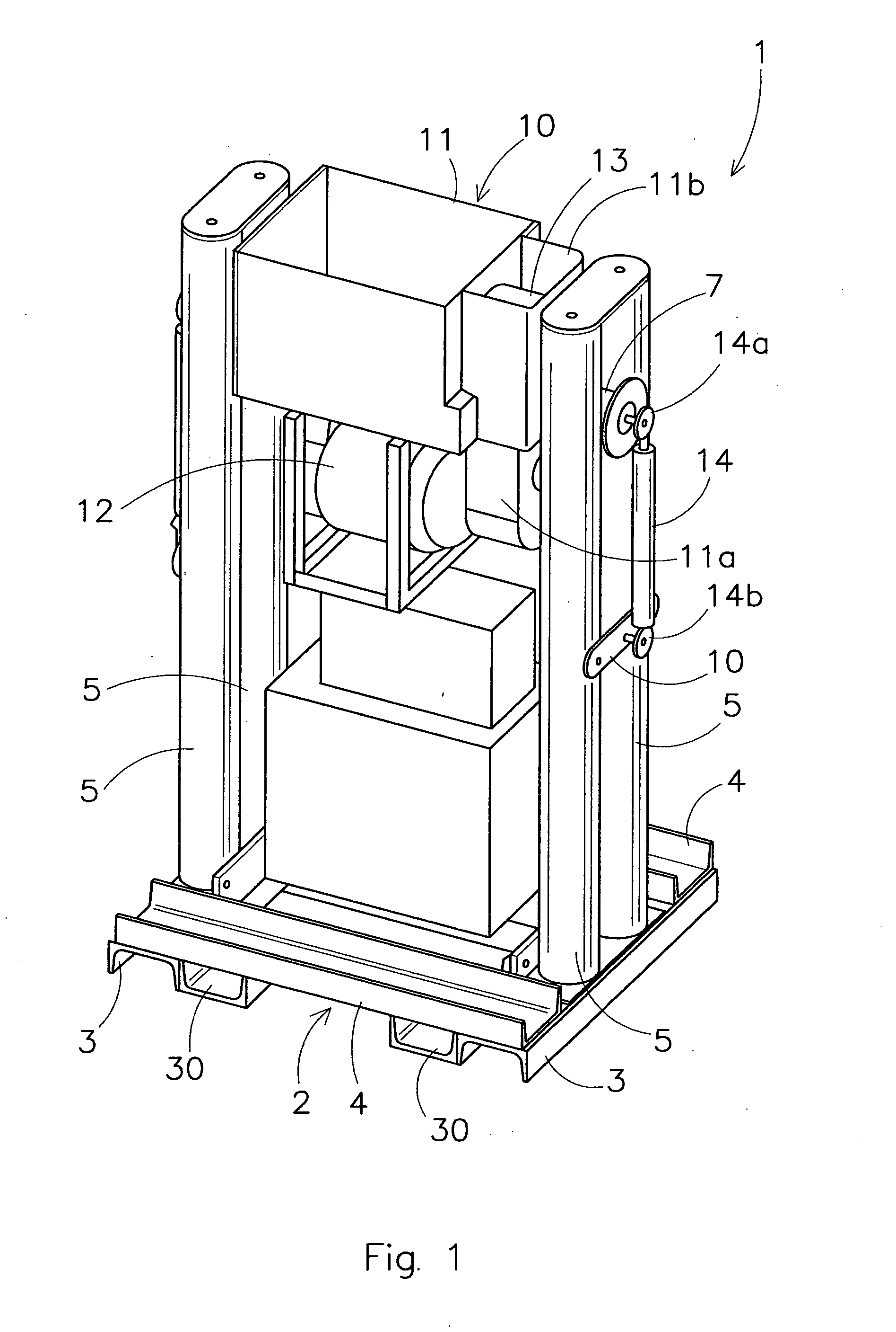
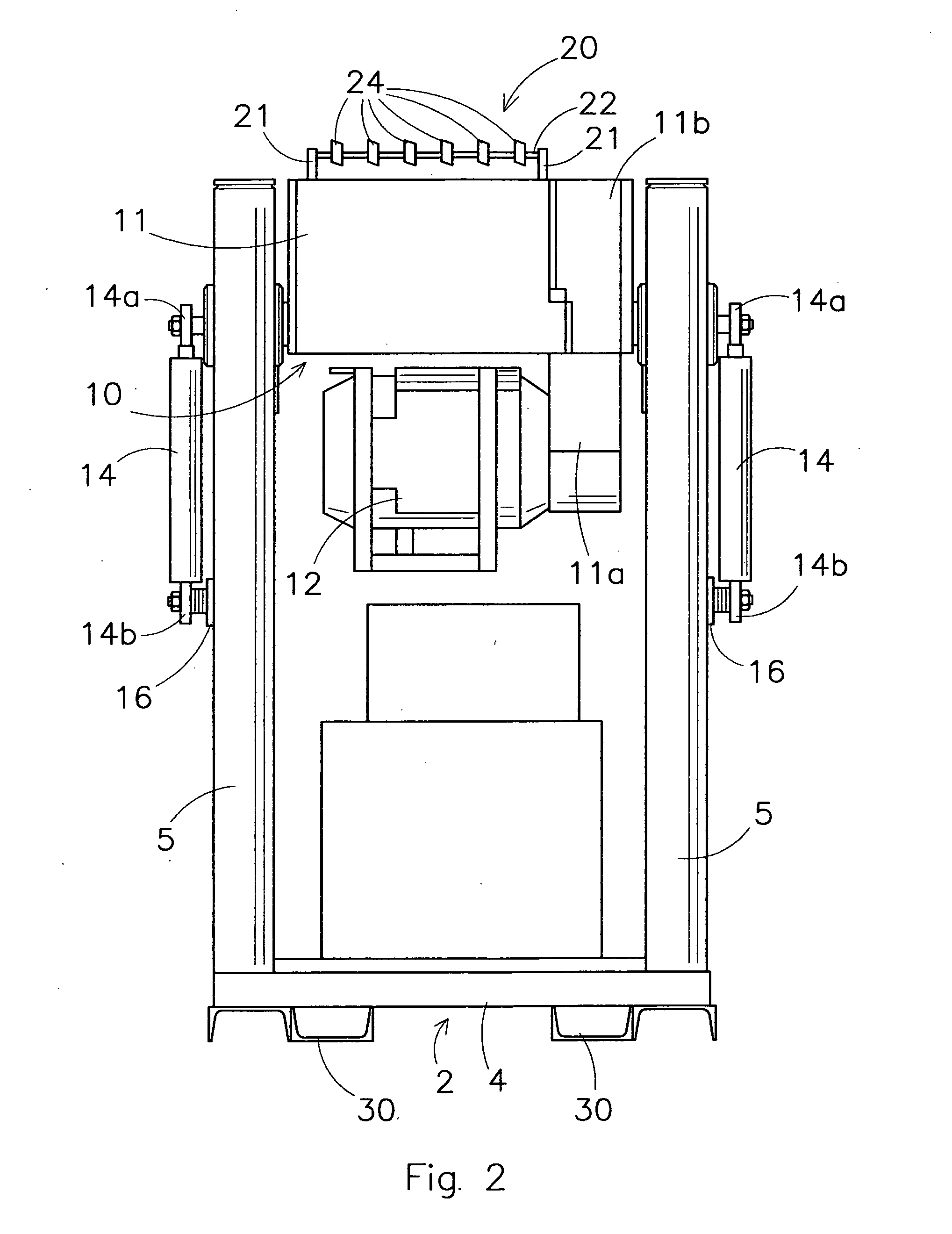
[0025] In FIGS. 1-3 is shown a milling arrangement 1. The milling arrangement 1 comprises a support base 2. In the shown example the support base 2 comprise a support frame which is formed of longitudinal beams 3 and lateral beams 4 in this particular example each with a U-shaped cross section. The support base 2 could however also be of a different structure, e.g. out of other types of beams or even formed as a single support plate.

[0026] On each side of the base 2 on the beams 3 is placed a pair of two spaced apart tubular guiding elements 5 with a cylindrical outer shape. The tubular guiding elements 5 extend from the support base 2 upwardly and parallel to each other. As is best seen in FIG. 3 between the tubular guiding elements 5 a space 6 is present in which a guiding roll 7 is moveable.

[0027] The milling arrangement 1 comprises a milling device 10. The milling device 10 comprises a casing 11 in which the milling tool 20 that will be described in more detail below is rotata...


PUM

PropertyMeasurementUnit
heightaaaaaaaaaa
movementaaaaaaaaaa
shapeaaaaaaaaaa

Abstract

The invention relates to a vehicle with a milling arrangement on top. The milling arrangement includes a milling device for grinding an upper tunnel wall surface like tunnel ceilings of traffic tunnels. Such a vehicle with the milling arrangement according to the invention is suitable for treating tunnel walls such that a desired surface roughness and the removal of carbon black results. This assures that a lining which is applied to the tunnel ceiling and wall surface is sufficiently attached to said surfaces.

Description

CROSS-REFERENCE TO RELATED APPLICATIONS [0001] This application claims the benefit of European Application No. EP 05077162.5, filed Sep. 21, 2005, the contents of which are incorporated herein by reference. BACKGROUND OF THE INVENTION [0002] The present invention relates to a milling arrangement for tunnel walls more particular tunnel ceilings. Such a device is placed on a vehicle to treat tunnel ceilings of traffic tunnels. [0003] As a consequence of exhaust fumes produced by the traffic traveling through tunnels the tunnel walls become covered with a layer of carbon black. In case of a fire in the tunnel the carbon black layer as well as the concrete can start to bum due to very high temperatures which typically occur in case of tunnel fires. In order to improve the safety of existing tunnels it is desirable to apply a fire resistant lining to the tunnel ceiling in order to avoid the hazard of a quick spreading of the fire via the ceiling surface. To assure a sufficient attachment...

Claims


Application Information

Patent Timeline
Patent Type & Authority Applications(United States)
IPC IPC(8): E21C25/00
CPCB24B27/0007B28D1/181E21D11/381
Inventor VAN HOUTEN, ADRIANUS GERARDUS
Owner BLASTRAC
Why Eureka
Try Eureka