Image encoding method, device thereof, and control program thereof

a control program and image encoding technology, applied in the direction of color television with bandwidth reduction, signal generator with optical-mechanical scanning, signal system, etc., can solve the problems of inability to perform quantization suitable. , to achieve the effect of finely quantizing an entire image frame, and reducing the amount of codes

Inactive Publication Date: 2007-06-21
NEC CORP
View PDF9 Cites 38 Cited by
  • Summary
  • Abstract
  • Description
  • Claims
  • Application Information

AI Technical Summary

Benefits of technology

[0030] The present invention comprises a means for setting a dead zone width corresponding to the visual sensitivity of a transformation coefficient in a frequency domain or the visual sensitivity of a block comprising a plurality of transformation coefficients as constituent elements in a spatial domain in the transform encoding technique for images. This makes it possible to provide a quantization function corresponding to the visual sensitivity of a transformation coefficient in a frequency domain and the visual sensitivity of a block comprising a plurality of transformation coefficients as constituent elements in a spatial domain.
[0031] The present invention can reduce the amount of codes wastefully consumed for a transformation coefficient with low visual sensitivity in a frequency domain and a block with low visual sensitivity in a spatial domain independently of the quantization width determined by a quantization parameter. Reducing the amount of codes makes it possible to quantize an entire image frame more finely than in the conventional scheme and encode a transformation coefficient with high visual sensitivity in a frequency domain and a block with high visual sensitivity in a spatial domain with high image quality.

Problems solved by technology

The first problem is that the respective blocks constituting an MB do not necessarily have the same pattern.
In such a case, the conventional technique cannot perform quantization suitable for the pattern of each block constituting an MB.
The second problem is that in moving image encoding operation in which each block constituting an MB allows independent intra-frame prediction or each block constituting an MB allows inter-frame prediction using an independent vector, the performance of minimizing a prediction error (to be referred to as prediction performance hereinafter) varies for each block constituting an MB.
In such a case, the conventional technique cannot perform quantization suitable for the prediction performance of each block constituting an MB.
The third problem is that the distribution of orthogonal transformation coefficients corresponding to the coordinates (to be referred to as spatial frequencies hereinafter) in a block varies due to the first and second reasons, and the respective blocks constituting an MB do not exhibit a uniform distribution.
In such a case, the conventional technique cannot perform quantization suitable for the distribution of the orthogonal transformation coefficients of each block.
Owing to these problems, in the conventional technique, a quantization parameter for an MB cannot help but be determined in accordance with the highest visual sensitivity in a frequency domain in the MB or a block exhibiting the highest visual sensitivity in a spatial zone in the MB.
That is, unnecessary information amounts are assigned to transformation coefficients exhibiting low visual sensitivity.

Method used


Image

  • Image encoding method, device thereof, and control program thereof
  • Image encoding method, device thereof, and control program thereof
  • Image encoding method, device thereof, and control program thereof

Examples


first embodiment

[0056] The first embodiment of the present invention will be described.

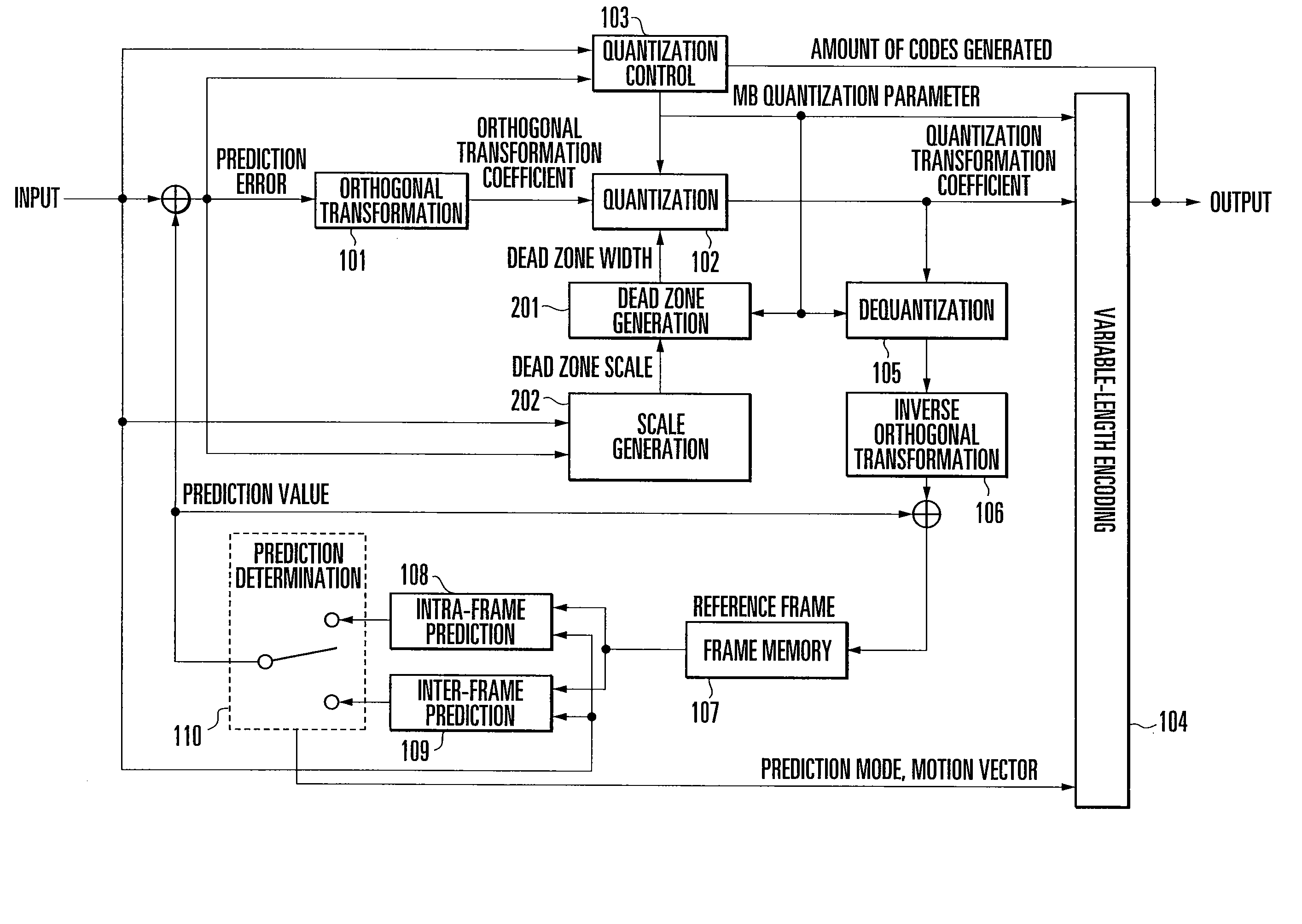
[0057]FIG. 3 shows an example of the arrangement of the first embodiment.

[0058] In this embodiment, an image frame forming a moving image is divided into a plurality of areas called macroblocks (MBs), and each block obtained by further dividing each MB is encoded.

[0059] A prediction value supplied from an intra-frame prediction device 108 which performs prediction from inside the same image frame reconstructed in the past or an inter-frame prediction device 109 which performs prediction from a past image frame reconstructed in the past is subtracted from the above MB. The MB signal from which the prediction value has been subtracted is called a prediction error signal.

[0060] The above prediction error signal is divided into smaller blocks (to be simply referred to as blocks hereinafter), and each block is transformed from a spatial domain into a frequency domain by an orthogonal transformation device 101.

[00...

second embodiment

[0127] The second embodiment of the present invention will be described.

[0128]FIG. 11 shows the arrangement of the second embodiment of the present invention. The arrangement of the second embodiment comprises a spatial frequency dead zone scale generator 203 in place of the block dead zone scale generator 202 in the arrangement of the first embodiment. The spatial frequency dead zone scale generator 203 supplies a dead zone scale dz_scale(b,i,j) (0≦b≦15, 0≦i≦3, 0≦j≦3) corresponding to the bth block in the raster scan order in an image frame to a dead zone generator 201.

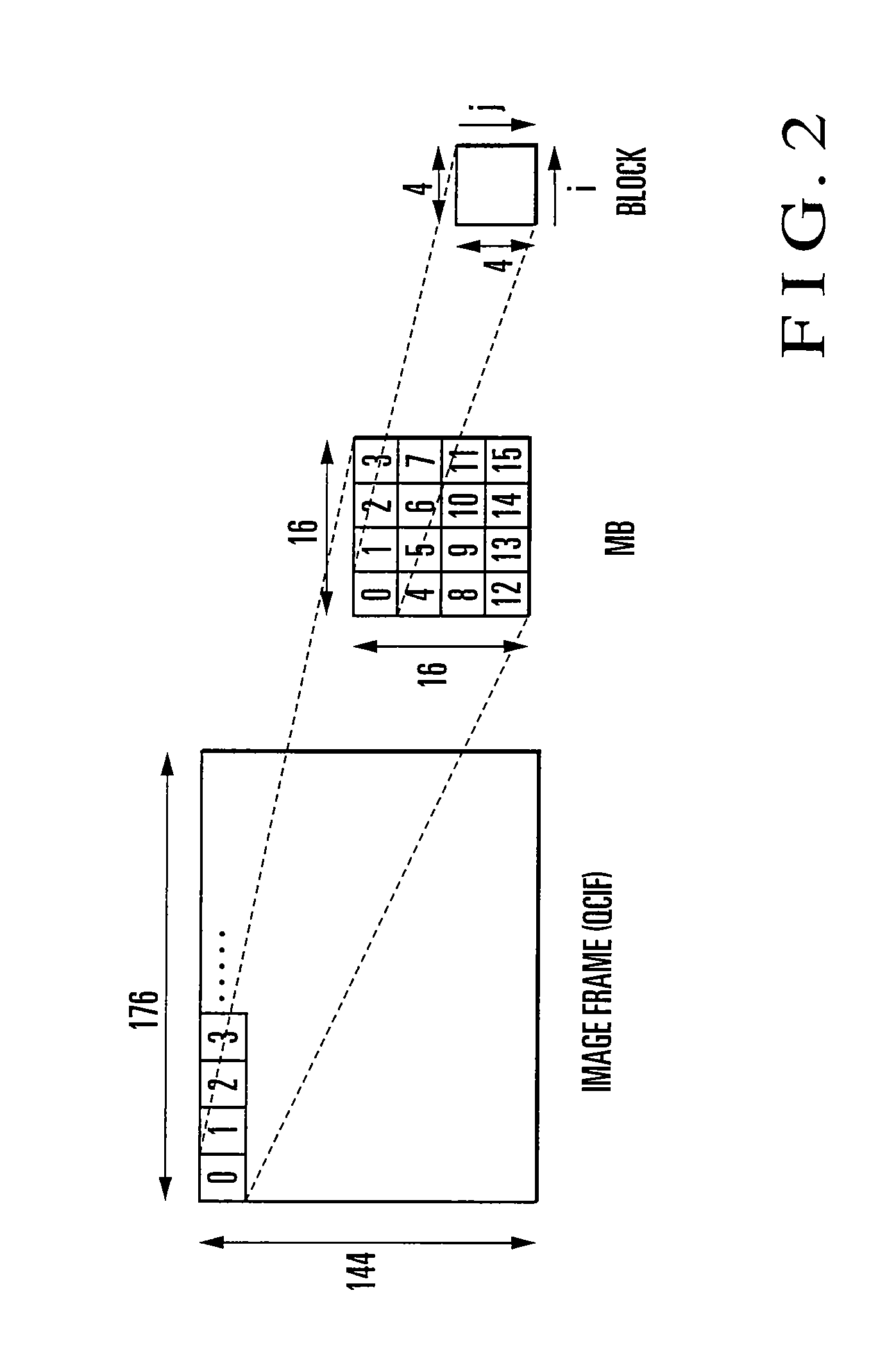
[0129] For a concrete explanation, assume that in the following description, the size of an image frame is a QCIF (176×144) size, the size of an MB is a 16×16 size, and the size of a block is a 4×4 size. Obviously, however, the present invention can be applied a case wherein other sizes are used.

[0130] The spatial frequency dead zone scale generator 203 which is a characteristic feature of the second embodiment wi...

third embodiment

[0167] The third embodiment of the present invention will be described.

[0168]FIG. 16 shows the arrangement of the third embodiment of the present invention. The arrangement of the third embodiment comprises a hybrid dead zone scale generator 204 in place of the block dead zone scale generator 202 in the arrangement of the first embodiment. A spatial frequency dead zone scale generator 203 supplies a dead zone scale dz_scale(b,i,j) (0≦b≦15, 0≦i≦3, 0≦j≦3) corresponding to the bth block in the raster scan order in an image frame to a dead zone generator 201.

[0169] For concrete explanation, assume that in the following description, the size of an image frame is a QCIF (176×144) size, the size of an MB is a 16×16 size, and the size of a block forming an MB is a 4×4 size. Obviously, however, the present invention can be applied a case wherein other sizes are used.

[0170] In addition, the hybrid dead zone scale generator 204 as a characteristic feature of the third embodiment will be des...


PUM


Abstract

A block dead zone scale generator (202) receives an image signal and a prediction error, analyzes the pattern or prediction performance of a target block, and outputs a dead zone scale suitable for the pattern or prediction performance of the block. A dead zone generator (201) receives a dead zone scale from the block dead zone scale generator (202) and an MB quantization parameter from a quantization control device (103), calculates a dead zone width from the zone scale and the MB quantization parameter, and outputs the dead zone width. A quantization device (102) quantizes an orthogonal transformation coefficient supplied from an orthogonal transformation device (101) by using a dead zone from the dead zone generator (201), and outputs a quantized transformation coefficient. This makes it possible to realize quantization with arbitrary strength for each transformation coefficient and for each block comprising a plurality of transformation coefficients as constituent elements, thereby providing a high-quality image encoding technology.

Description

TECHNICAL FIELD [0001] The present invention relates to an image encoding method, a device thereof, and a control program thereof and, more particularly, to an image encoding method of performing adaptive quantization for an improvement in subjective image quality, a device thereof, and a control program thereof. BACKGROUND ART [0002] A conventional technique will be described with reference to the accompanying drawings. [0003] Hybrid moving image encoding as a conventional technique based on an orthogonal transformation device and a prediction device (intra-frame prediction / inter-frame prediction) will be described below with reference to FIG. 1. [0004] According to the conventional technique, an image frame forming a moving image is divided into a plurality of areas called macroblocks (MBs), and each block obtained by further dividing each MB is encoded. FIG. 2 shows the arrangement of an AVC (Advanced Video Coding: ISO / IEC 14496-10) image frame as a concrete example of the arrang...

Claims


Application Information

Patent Timeline
Patent Type & Authority Applications(United States)
IPC IPC(8): H04N11/04H04N7/12H04N19/124H04N19/136H04N19/137H04N19/14H04N19/157H04N19/159H04N19/176H04N19/196H04N19/60
CPCH04N19/105H04N19/176H04N19/149H04N19/152H04N19/126H04N19/136H04N19/61H04N19/132H04N19/60
Inventor CHONO, KEIICHISENDA, YUZO
Owner NEC CORP
Why Eureka
Try Eureka