
Active vibrational noise control apparatus

a technology of vibration and control apparatus, which is applied in the direction of noise generation, ear treatment, instruments, etc., can solve the problems of low noise canceling process per second, high manufacturing cost, and inability to control the vibration of the control apparatus, so as to reduce the processing ability of the cpu, reduce the processing cost, and increase the freedom

Active Publication Date: 2007-06-21
HONDA MOTOR CO LTD
View PDF10 Cites 28 Cited by
  • Summary
  • Abstract
  • Description
  • Claims
  • Application Information

AI Technical Summary

Benefits of technology

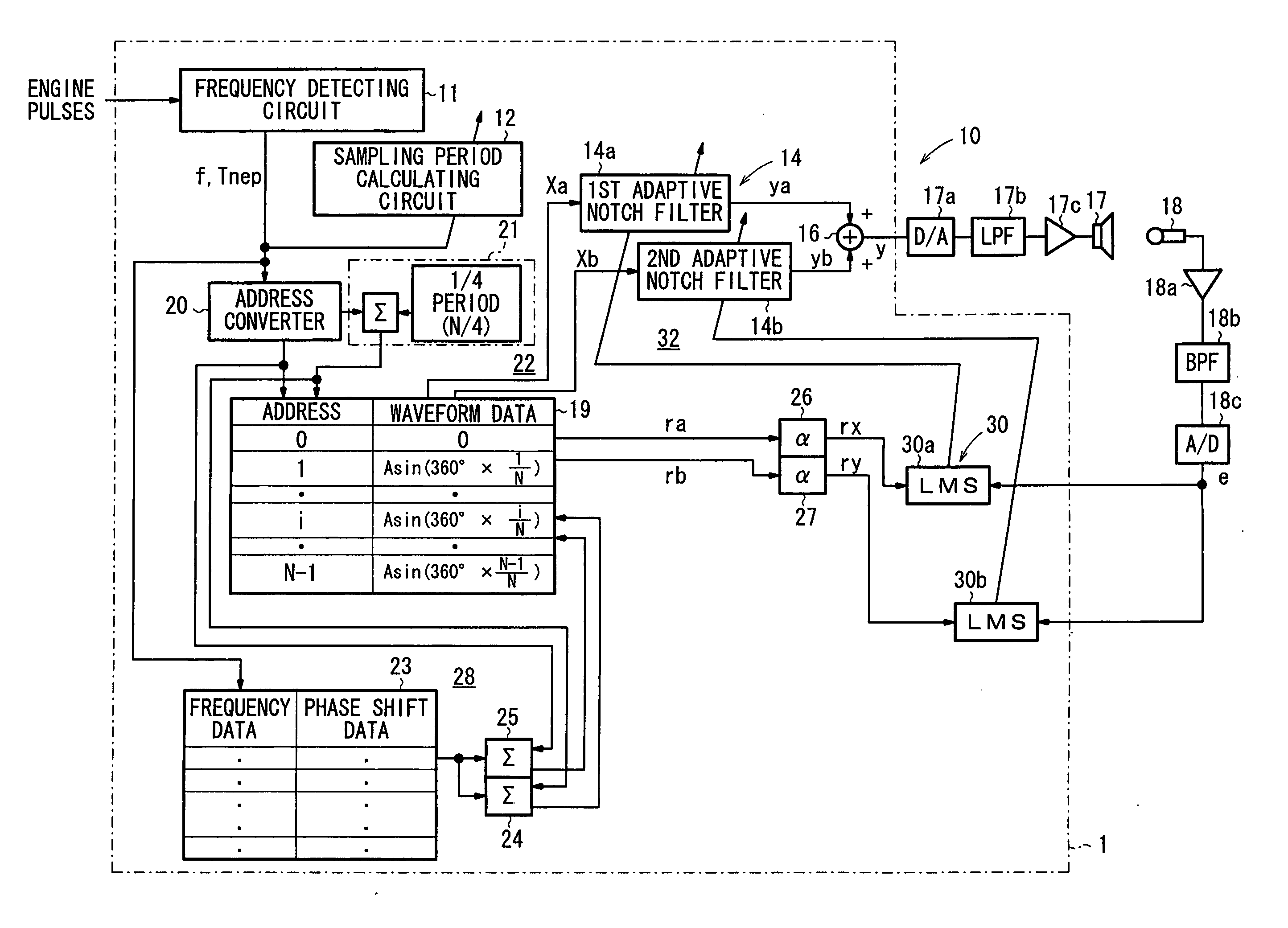
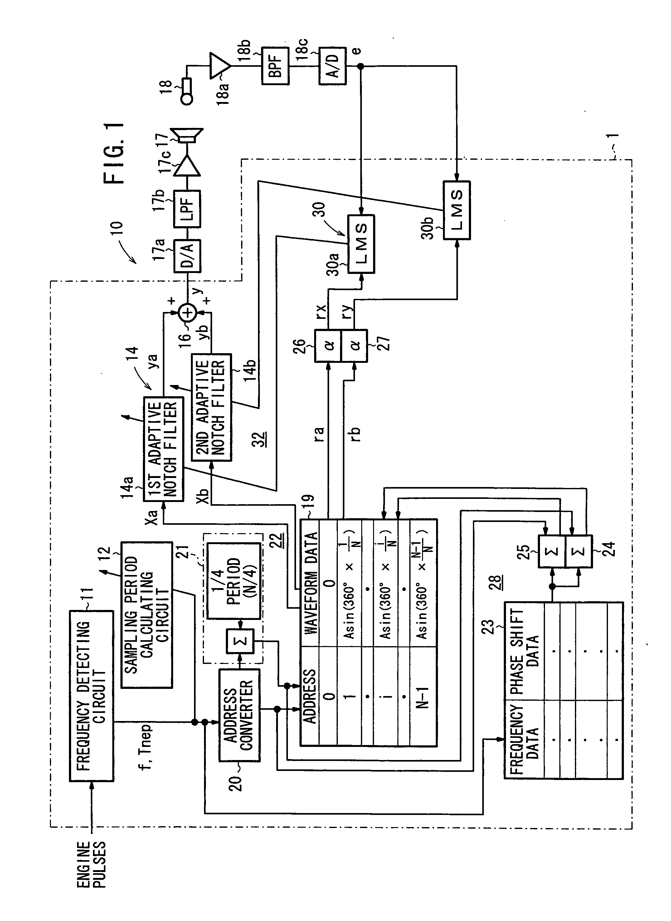
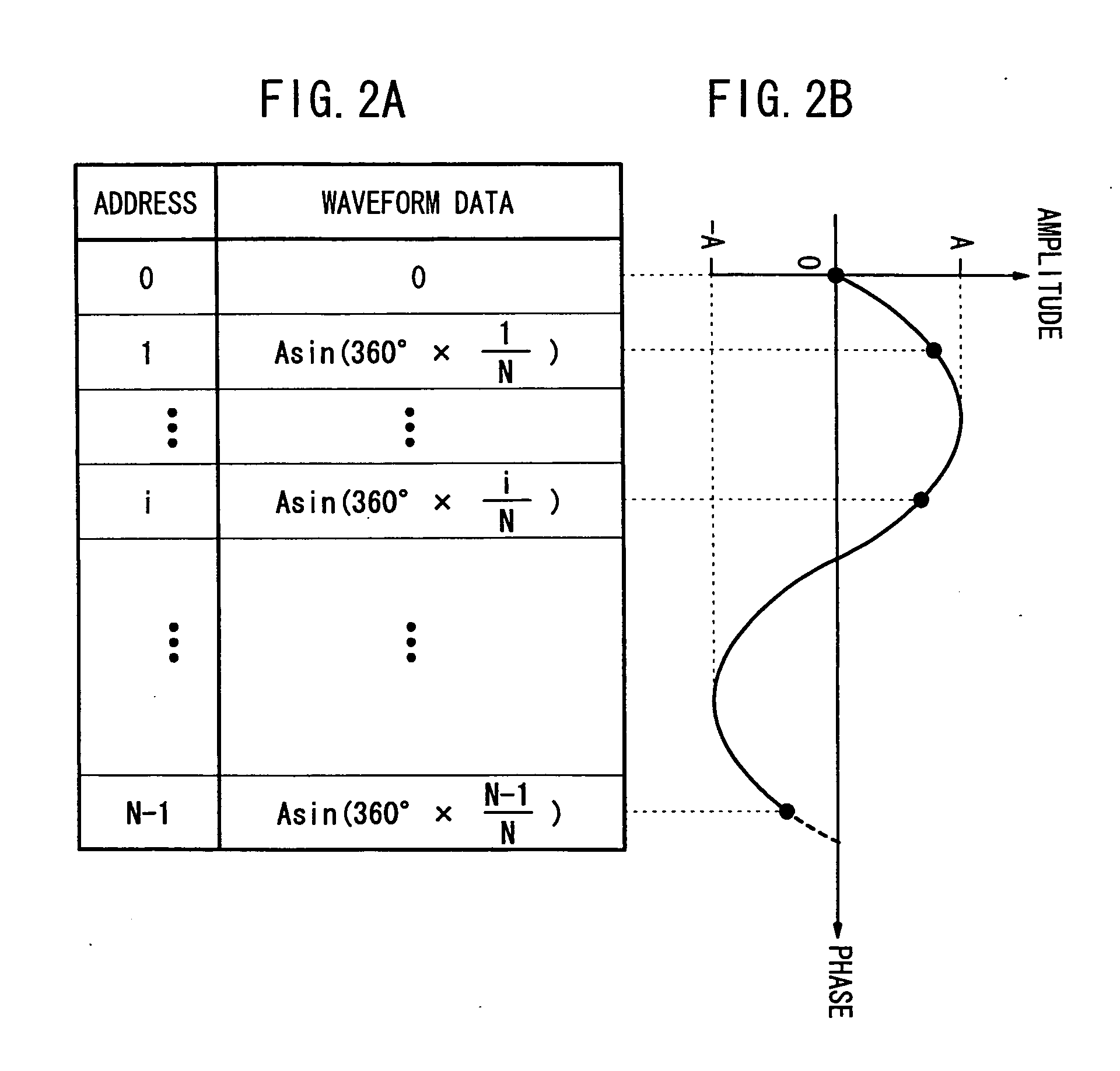
The present invention provides an active vibration noise control apparatus that can be designed with increased freedom and can achieve a wider control range. It is capable of reducing noise in a space where noise is transmitted from a noise source, even if the engine rotational speed fluctuates due to unconscious small actions made by the user on the accelerator pedal. The apparatus uses a control sound source to generate a base sound to cancel out the noise. The apparatus also includes a residual noise detecting system to further reduce noise in the space. The base sound is generated based on the engine vibration noise generated by the noise source and the residual noise detected in the space. The apparatus uses a waveform data table to store waveform data of the engine vibration noise and a sampling period calculating means to determine the base period of the base sound. The sampling period calculating means uses the identical division number of the base period to calculate the sampling period. The apparatus can be designed with increased freedom and can achieve a wider control range.

Problems solved by technology

Therefore, the active vibrational noise control apparatus 1 requires a storage means of large storage capacity and is costly to manufacture.
If the sampling period ts is longer than the noise canceling ability limit sampling period tmax, then the number of noise canceling processes per second is so small that no desired noise canceling capability is available.
Therefore, if the control range is to be widened, then a fast high-performance CPU is needed, making the active vibrational noise control apparatus highly costly to manufacture.
The conventional variable sampling technology is also problematic in that since the number of waveform data and the division number are equal to each other, the number of waveform data and the division number N are a natural number, and the freedom with which to design the active vibration noise control apparatus is small.

Method used


Image

  • Active vibrational noise control apparatus
  • Active vibrational noise control apparatus
  • Active vibrational noise control apparatus

Examples


1st embodiment

[0105]The number of updates in one period of the base signal X is set to a division number m=m1.

[0106]According to the first embodiment, the division number m1 is determined by dividing a first upper limit base period TU1 of a control range Tca1 shown in FIG. 4 by the noise canceling ability limit sampling period tmax according to the equation (2) shown below. The control range Tca1 refers to a predetermined range (particular range) within a control range Ttotal.

m1=TU1 / tmax  (2)

where the division number m1 is a positive real number. According to the conventional sampling technology, the division number N is a natural number.

[0107]The first upper limit base period TU1 may not be a longest period in the control range, but may be set to a shorter particular base period.

[0108]Then, a first identical division number lower limit base period TL1 which is a shorter period in the control range Tca1 of the base period Tnep is determined by multiplying the division number m1 determined accordi...

2nd embodiment

[0130]A process according to a second embodiment, which is performed when the detected base period Tnep is shorter than the first identical division number lower limit base period TL1 at the lower limit of the control range Tca1 (the engine rotational speed is higher), as shown in FIG. 4, will be described below. According to the second embodiment, a wider control range Ttotal can be controlled by the same CPU, i.e., a CPU having the same processing ability limit, or in other words, without making the processing ability limit sampling period tmin shorter.

[0131]For an easier understanding of the second embodiment, the identical division number lower limit base period TL1 shown in FIG. 4 is also referred to as a second upper limit base period TU2.

[0132]In the second embodiment, a value produced when the second upper limit base period TU2 is divided by the noise canceling ability limit sampling period tmax is used as a second division number m2 (real number), as with the equation (2).

[...

3rd embodiment

[0142]Actually, the engine rotational speed in a cruise control mode (constant speed control) suffers fluctuations of ±10 [rpm] due to air-fuel combustion fluctuations in the engine when the engine rotational speed is 2000 [rpm], for example. When the engine operates not in the cruise control mode, the engine rotational speed tends to fluctuate because of an unconscious small action made by the user on the accelerator pedal for driving the vehicle at a constant speed.

[0143]Therefore, if the detected base period Tnep is of a value close to the second upper limit base period TU2 in FIG. 6, then switching occurs between the sampling period characteristic curve C1 and the sampling period characteristic curve C2. Since the division number m switches between the division number m1 and the division number m2, the number of updates in the active control varies, making the active control unstable. Consequently, the noise canceling capability is liable to vary slightly.

[0144]According to the ...


PUM


Abstract

While a vehicle incorporating an active vibration noise control apparatus is decelerating, hysteresis is given if an operating point moves from an operating point on a sampling period characteristic curve to an operating point on another sampling period characteristic curve. Even if a base period detected depending on noise contains fluctuations, a smooth noise control process is performed. Since a division number produced when the base period is divided by a sampling period is a real number, the freedom of design is widened. Less strict limits are posed on the processing capability of a CPU of the active vibration noise control apparatus to provide a wider control range.

Description

BACKGROUND OF THE INVENTION[0001]1. Field of the Invention[0002]The present invention relates to an active vibrational noise control apparatus for actively controlling vibrational noise with adaptive notch filters, and more particularly to an active vibrational noise control apparatus for use on vehicles.[0003]2. Description of the Related Art[0004]FIG. 15 of the accompanying drawings shows in block form an electric arrangement of a general active vibrational noise control apparatus 1 for actively controlling vibrational noise with an adaptive notch filter.[0005]As shown in FIG. 15, the active vibrational noise control apparatus, generally denoted by 1, has an adaptive notch filter 2 and a reference signal generator 3 which are supplied with a base signal x(n) generated from the frequency of vibrational noise that is to be controlled.[0006]The reference signal generator 3 generates and outputs a reference signal r(n) which takes into account transfer characteristics from a speaker 4...

Claims


Application Information

Patent Timeline
Patent Type & Authority Applications(United States)
IPC IPC(8): A61F11/06
CPCG10K11/178G10K11/17823G10K11/17854G10K11/17855G10K11/17883
Inventor SAKAMOTO, KOSUKEINOUE, TOSHIOTAKAHASHI, AKIRAKOBAYASHI, YASUNORI
Owner HONDA MOTOR CO LTD
Learn More