Speaker device and mobile phone

a speaker device and mobile phone technology, applied in the direction of transducer details, mechanical vibration separation, electrical transducers, etc., can solve the problem that the speaker device is hardly applied, and achieve the effect of reducing manufacturing costs, reducing sensitivity and efficiency, and thin speaker devices

Inactive Publication Date: 2007-06-21
PIONEER CORP +1
View PDF9 Cites 144 Cited by
  • Summary
  • Abstract
  • Description
  • Claims
  • Application Information

AI Technical Summary

Benefits of technology

[0040] Namely, in this manner, since the magnetic circuit includes no pair of plates, the sensitivity and efficiency are slightly reduced as compared with the above-mentioned speaker device by the amount. Inversely, the manufacturing cost can be reduced. Thus, in consideration of the sensitivity and efficiency of the electronics such as the mobile phone and the manufacturing cost, the speaker device according to this manner is preferably usable as the speaker device for the receiver of the mobile phone, for example. In addition, since the pair of plates are not provided, the height of the speaker device, corresponding to the vibration direction of the diaphragm and the voice coil, can be small by the amount, and the thinner speaker device can be realized.
[0041] In another embodiment of the above speaker device, in consideration of the sensitivity, the efficiency and the manufacturing cost, the magnetic circuit may include the yoke, the magnet formed into the rectangle shape and arranged on the upper surface of the yoke, the magnetic body oppositely arranged on the upper surface of the yoke with the constant space to the magnet, and further the magnetic gap between the magnet and the magnetic body. Thereby, since the magnetic circuit does not include the pair of plates, the height of the speaker device, corresponding to the vibration direction of the diaphragm and the voice coil, can be small by the amount, and the thinner speaker device can be realized.

Problems solved by technology

However, the speaker device according to the above-mentioned References-1 and 2 structurally becomes thick in the vibration direction of the diaphragm, and there is such a problem that the speaker device is hardly applied to a recent mobile phone of a thin-type.

Method used


Image

  • Speaker device and mobile phone
  • Speaker device and mobile phone
  • Speaker device and mobile phone

Examples


first embodiment

(Configuration of Speaker Device)

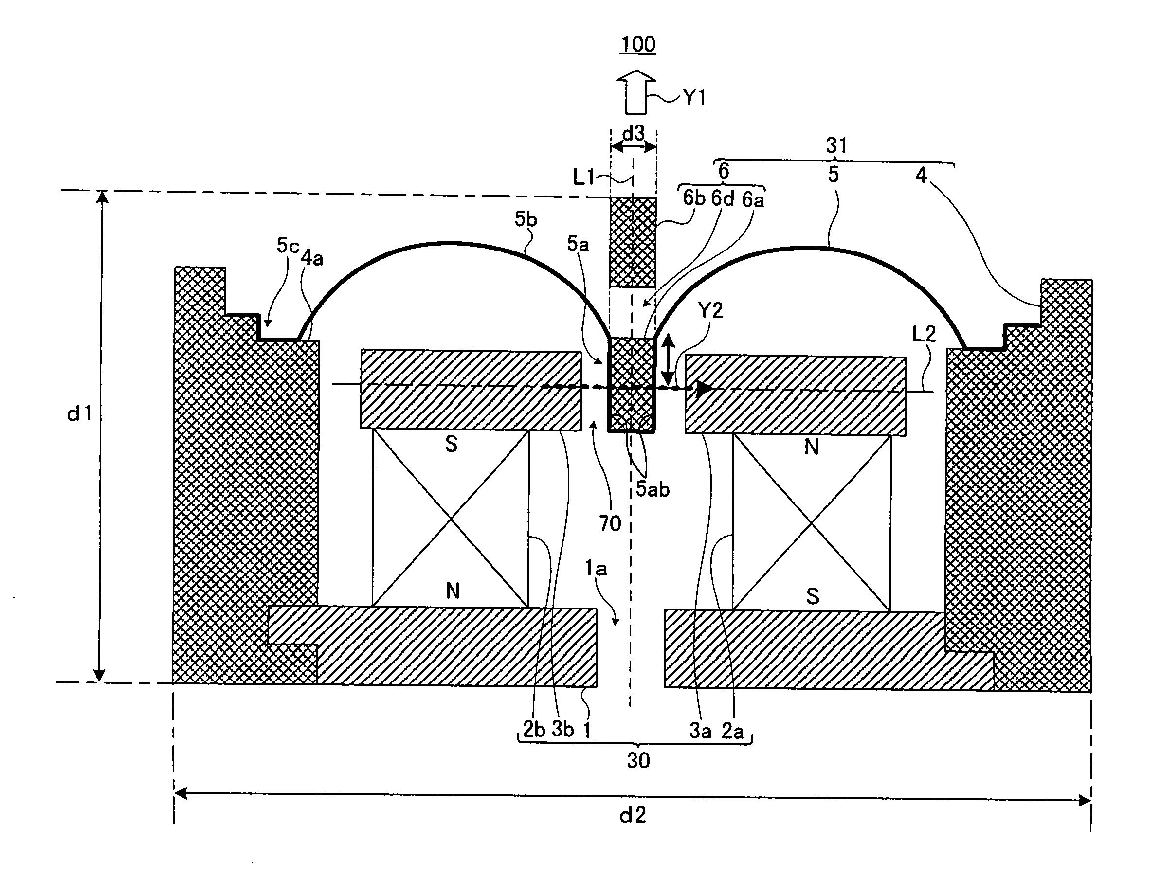
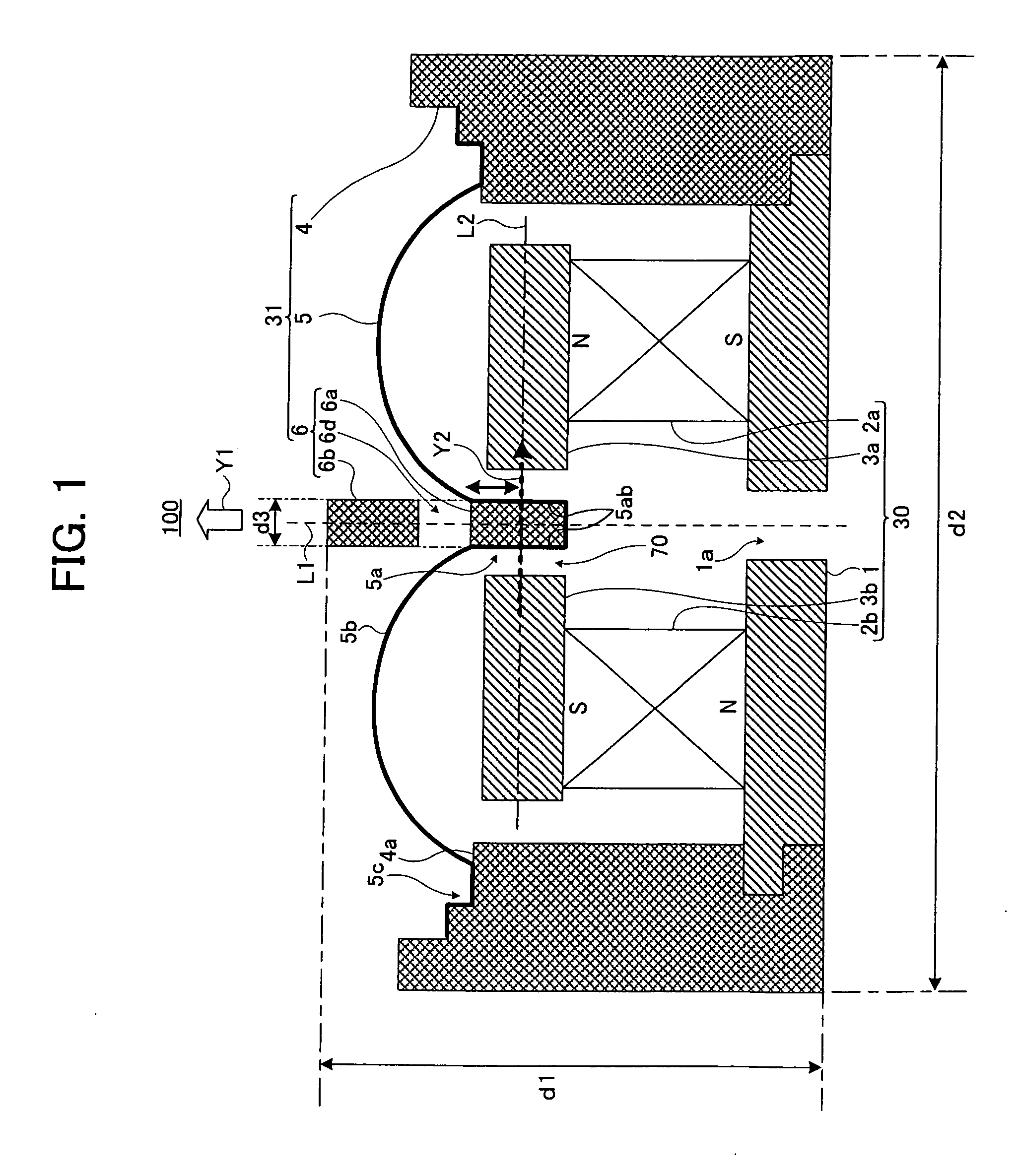
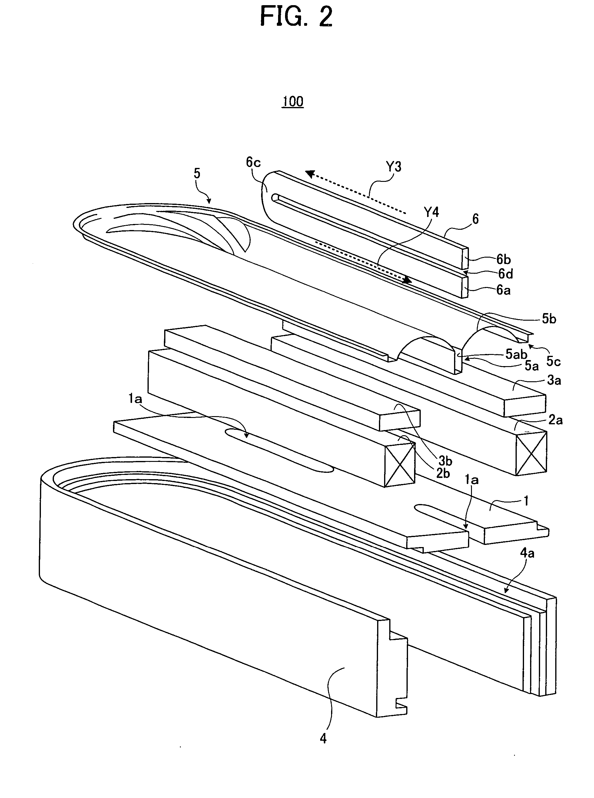
[0064]FIG. 1 schematically shows a cross-sectional configuration of a speaker device 100 according to a first embodiment of the present invention. In addition, FIG. 1 shows a cross-sectional view of the speaker device 100 when cut by a plane passing through a central axis L1 thereof. FIG. 2 shows a one-side disassembly perspective view of the speaker device 100 shown in FIG. 1 when cut by the central axis L1. Hereinafter, a description will be given of the configuration of the speaker device 100 according to the first embodiment of the present invention.

[0065] The speaker device 100 mainly includes an internal-magnet-type magnetic circuit 30 having a yoke 1, a pair of magnets 2a and 2b and a pair of plates 3a and 3b, a frame 4, and a vibration system 31 having a diaphragm 5 and a voice coil 6. Hereinafter, for convenience of explanation, when each of the magnets and / or each of the plates are distinguished, they are individually expressed, like “ma...

second embodiment

[0099] Next, a description will be given of a configuration of a speaker device 200 according to a second embodiment of the present invention, with reference to FIG. 6. FIG. 6 shows a cross-sectional view of a speaker device 200 of the second embodiment when cut by a plane passing through the central axis L1. Hereinafter, the same reference numerals are given to the same components as those common with the first embodiment, and explanations thereof are simplified or omitted.

[0100] When the second embodiment is compared with the first embodiment, their configurations are substantially common. However, the number of magnets 2 and the number of plates 3 are different between the second embodiment and the first embodiment.

[0101] Concretely, though the speaker device 200 according to the second embodiment includes the magnet 2b and the plate 3b, it does not include the magnet 2a and the plate 3a. Instead, in the second embodiment, the speaker device 200 includes a magnetic body 8 at th...

third embodiment

[0104] Next, a description will be given of a configuration of a speaker device 300 according to a third embodiment of the present invention, with reference to FIG. 7. FIG. 7 shows a cross-sectional view of the speaker device 300 according to the third embodiment when cut by a plane passing through the central ax is L1. Hereinafter, the same reference numerals are given to the components common with those of the first embodiment, and explanations thereof are simplified or omitted.

[0105] When the third embodiment and the first embodiment are compared, their configurations are substantially common. However, the number of magnets in the third embodiment is larger than that of the first embodiment.

[0106] Concretely, the speaker device 300 according to the third embodiment further includes the pair of magnets 2c and 2d in addition to the pair of magnets 2a and 2b. In the present invention, in consideration of the manufacturing cost or in accordance with the specification, the speaker d...


PUM


Abstract

A speaker device includes a magnetic circuit which includes a magnetic gap, a diaphragm which has a recessed part arranged in the magnetic gap and extending in a direction substantially orthogonal with respect to an extending direction of a magnetic flux in the magnetic gap, and a voice coil which is formed into an annular shape and has a first parallel part extending in one direction and a second parallel part extending in a direction in parallel with the first parallel part and opposite to the first parallel part with a constant space. Particularly, the first parallel part and the second parallel part are arranged in a direction in parallel with an extending direction of the recessed part, respectively. The first parallel part is arranged in the recessed part to be positioned in the magnetic gap, and the second parallel part is positioned above the recessed part.

Description

BACKGROUND OF THE INVENTION [0001] 1. Field of the Invention [0002] The present invention relates to a configuration of a speaker device preferably usable for a mobile phone. [0003] 2. Description of Related Art [0004] Conventionally, there is known a Ryffel-type speaker including a rectangular diaphragm and a liner voice coil arranged at a central part of the diaphragm (see “New Edition Encyclopedia of Speakers and enclosures” Tamon Saeki, Seibundo-Shinkosha, Aug. 1, 2002, Vol. 3, P. 40, for example). The speaker having a configuration of this kind is disclosed in Japanese Patent Applications Laid-open under No. 11-187484, No. 11-187485, No. 2000-350284 and No. 10-191494, which are referred to as References-1 to 4, respectively. [0005] The speaker according to Reference-1 mainly includes two diaphragms and a magnetic circuit including two, i.e., upper and lower magnetic gaps in parallel with each other and having opposite magnetic flux directions. At substantial centers on rear sur...

Claims


Application Information

Patent Timeline
Patent Type & Authority Applications(United States)
IPC IPC(8): H04R9/06H04R11/02H04R1/00
CPCB06B1/045H04R9/046H04R2499/11
Inventor MITOBE, KUNIOKONUMA, SHINSUKE
Owner PIONEER CORP
Why Eureka
Try Eureka