Large area substrate transferring method

a technology of large area and substrate, applied in the field of load lock chamber, can solve the problems of increasing the throughput of such high volume load lock chamber, increasing the pumping and venting speed, and requiring large and expensive hardwar

a technology of large area and substrate, applied in the field of load lock chamber, can solve the problems of increasing the throughput of such high volume load lock chamber, increasing the pumping and venting speed, and requiring large and expensive hardwar

US20070140814A1Inactive Publication Date: 2007-06-21APPLIED MATERIALS INC

Image

  • Large area substrate transferring method
  • Large area substrate transferring method
  • Large area substrate transferring method

Examples


Embodiment Construction

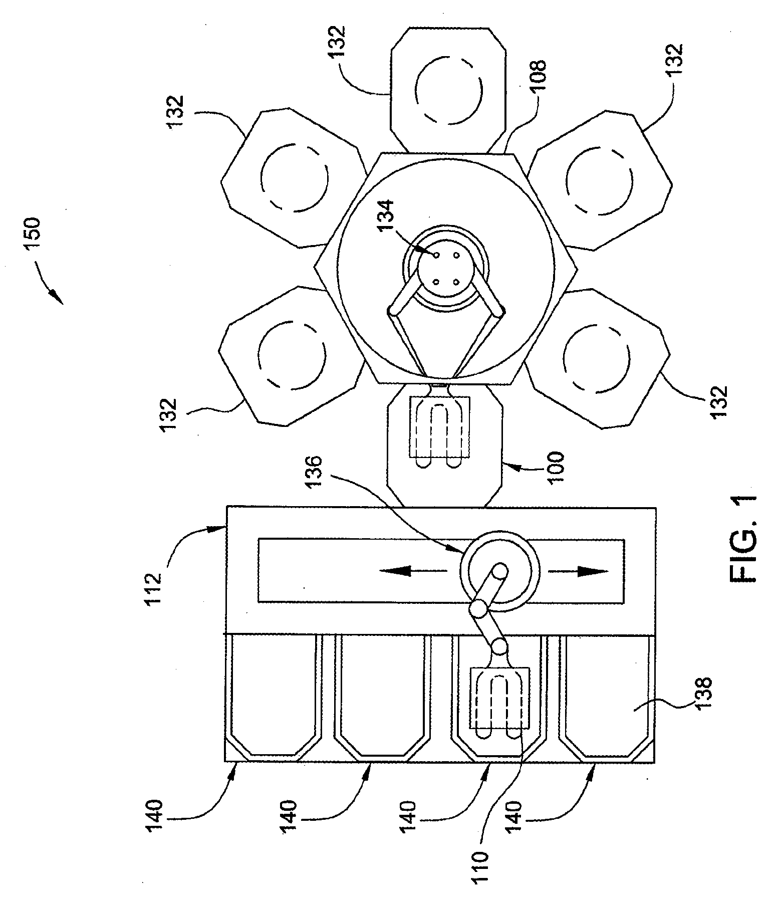
[0023] The invention generally provides a high volume / high throughput load lock chamber having multiple stacked substrate transfer chambers. The invention is illustratively described below utilized in a flat panel processing system, such as those available from AKT, a division of Applied Materials, Inc., Santa Clara, Calif. However, it should be understood that the invention has utility in other system configurations, wherever high throughput substrate transfer through a load lock chamber of large area substrates is desired.

[0024]FIG. 1 is a top plan view of one embodiment of a process system 150 suitable for processing large area substrates (e.g., substrates having a plan area greater than about 2.7 square meters). The process system 150 typically includes a transfer chamber 108 coupled to a factory interface 112 by a load lock chamber 100 having a plurality of single substrate transfer chambers. The transfer chamber 108 has at least one dual blade vacuum robot 134 disposed therei...


PUM


Abstract

A load lock chamber and method for transferring large area substrates is provided. In one embodiment, a load lock chamber suitable for transferring large area substrates includes a plurality of vertically stacked single substrate transfer chambers. The configuration of vertically stacked single substrate transfer chambers contributes to reduced size and greater throughput as compared to conventional state of the art, dual slot dual substrate designs. Moreover, the increased throughput has been realized at reduced pumping and venting rates, which corresponds to reduced probability of substrate contamination due to particulates and condensation.

Description

CROSS-REFERENCE TO RELATED APPLICATIONS [0001] This application is a division of co-pending U.S. patent application Ser. No. 10 / 832,795 (APPM / 008726), entitled “LOAD LOCK CHAMBER FOR LARGE AREA SUBSTRATE PROCESSING SYSTEM”, filed Apr. 26, 2004, which application claims benefit of U.S. Provisional Application Ser. No. 60 / 512,727 (APPM / 008726L), entitled “LOAD LOCK CHAMBER FOR LARGE AREA SUBSTRATE PROCESSING SYSTEM”, filed Oct. 20, 2003, both of which are hereby incorporated by reference in their entirety.BACKGROUND OF THE INVENTION [0002] 1. Field of the Invention [0003] Embodiments of the invention generally relate to a load lock chamber for transferring large area substrates into a vacuum processing system and methods of operation of the same. [0004] 2. Description of the Related Art [0005] Thin film transistors (TFT) are commonly used for active matrix displays such as computer and television monitors, cell phone displays, personal digital assistants (PDAs), and an increasing numb...

Claims


Application Information

Patent Timeline
21 Jun 2007
Publication
US20070140814A1
IPC
H01L21/677; B65G49/00; B65G49/06; H01L21/00; H01L21/68
CPC
B65G49/064; B65G49/067; B65G49/068; B65G2249/02; Y10S414/139; H01L21/67236; Y10S414/137; Y10S414/136
Inventors
KURITA, SHINICHI; BLONIGAN, WENDELL T.