
Turbomachine with variable stator

Active Publication Date: 2007-06-21
ROLLS ROYCE DEUT LTD & CO KG
View PDF4 Cites 38 Cited by
  • Summary
  • Abstract
  • Description
  • Claims
  • Application Information

AI Technical Summary

Benefits of technology

[0013] A broad aspect of the present invention is to provide a variable stator blade of the type specified above which, while avoiding the disadvantages of the state of the art, is characterized by exerting a highly effective influence on the peripheral flow due to a specific and problem-oriented block-wise definition of the profile skeleton lines along the blade height.

Problems solved by technology

The aerodynamic roadability and the efficiency of turbomachines, for example blowers, compressors, pumps and fans, is limited in particular by the growth and the separation of boundary layers in the area of the radial gaps between the blading and the casing or the hub, respectively, these gaps being necessary at the annulus rim for reasons of design.
In particular on rotatable variable stators, the radial gaps generated by the required recesses before and after the trunnion are pronounced and entail considerable flow losses.
However, due to failure provisions and design constraints, configurations of variable stators quite frequently exist which have only small size and where the rotary bases are not situated far enough upstream.
The state of the art does not provide any aerodynamically favorable solutions to this fundamental problem.
The general concept of boundary influencing of radial running gaps by changing the type of skeleton line along the blade height is provided in the state of the art, however, the known solutions are not adequate and, therefore, not effective, in particular for the flow conditions at a blade end with rotary base and two partial radial gaps.

Method used


Image

  • Turbomachine with variable stator
  • Turbomachine with variable stator
  • Turbomachine with variable stator

Examples


Embodiment Construction

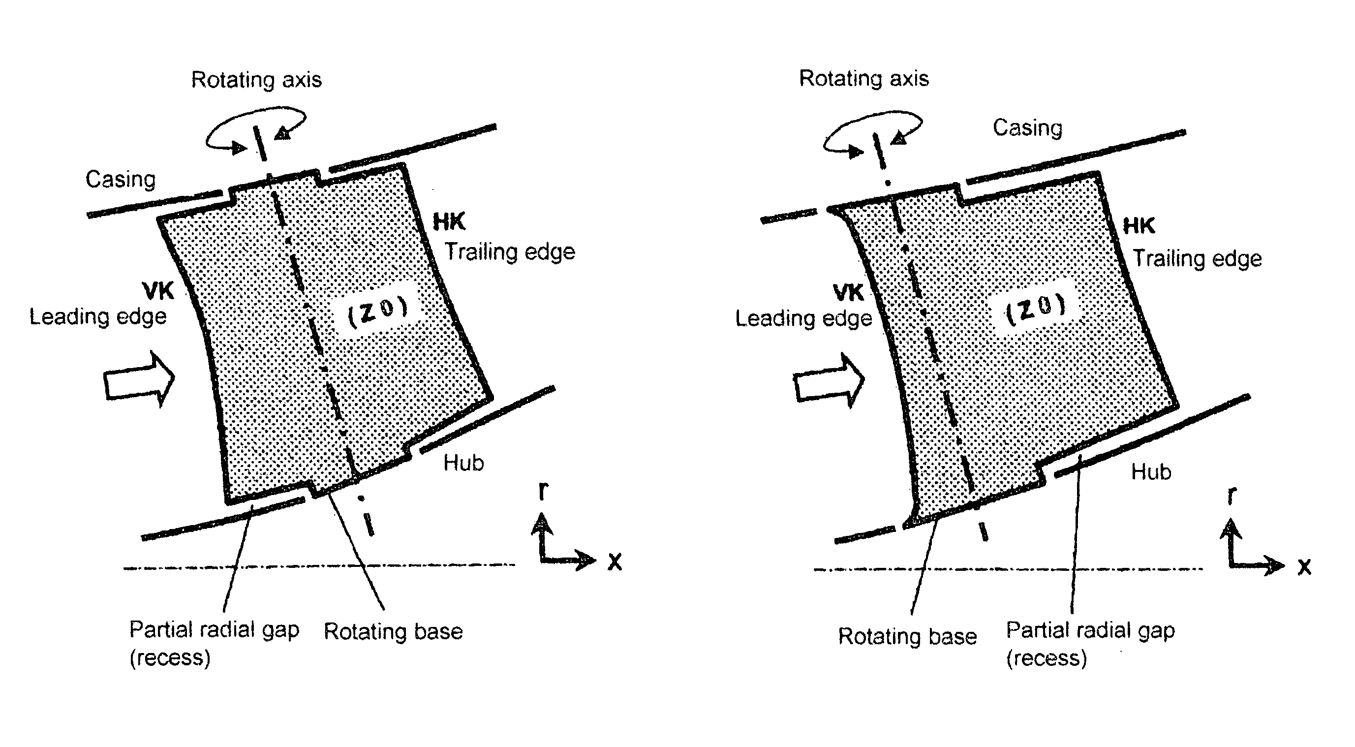
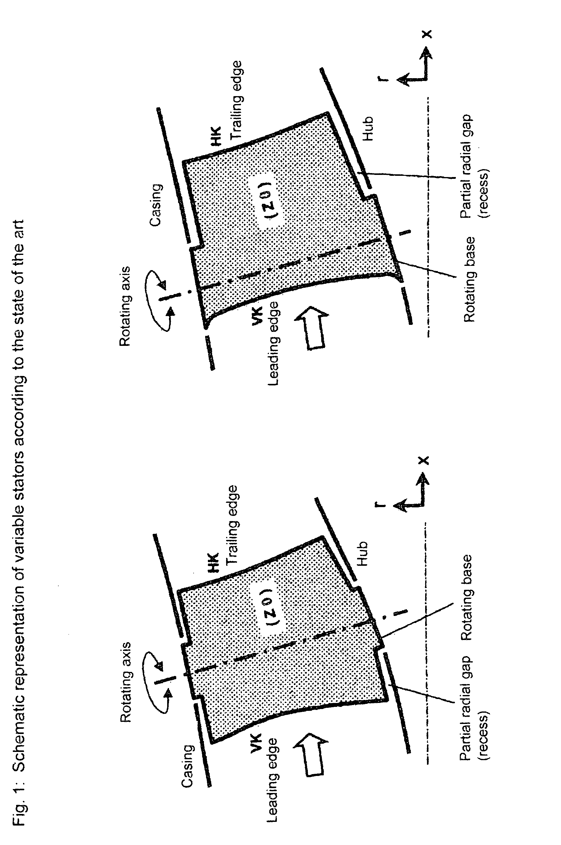
[0011] The present invention relates to stators which are rotatably borne on at least one blade end and are variable around a fixed rotating axis by a trunnion. As in all representations shown herein, inflow to the respective blade row is from the left to the right in the direction of the bold arrow.

[0012] The state of the art is disadvantageous in that the respective blade forms are designed, often deliberately, with low complexity regarding the shape of the skeleton line. Where different types of skeleton lines along the blade height are used, the character of the skeleton lines lacks block-wise markedness which would allow the profile pressure distribution in wall vicinity to be stronger influenced to obtain the max. possible degree of gap and peripheral flow steadying. In particular with variable stators, there is a lack of blade concepts with skeleton line variations along the blade height which appropriately combine a profile front load favorable in the blade mid area with a ...


PUM


Abstract

A variable stator of a turbomachine with a profile skeleton line extending along a meridional flow line, with the stator being radially divided into at least three zones (Z0, Z1, Z2) and with the respective radial inner and the radial outer profile skeleton line of each zone (Z0, Z1, Z2) being designed such that it satisfies the following equations: α*=α1-αPα1-α2S*=SPSwhere: P is any point of the profile skeleton line, α1 is the angle of inclination at the stator leading edge, α2 is the angle of inclination at the stator trailing edge, α* is the dimensionless, specific angle of the total curvature, S* is the dimensionless, specific extension, αp is the angle of the tangent at any point P of the profile skeleton line to the central meridional flow line, sp is the extension of the profile skeleton line at any point P, and S is the total extension of the profile skeleton line.

Description

[0001] This application claims priority to German Patent Application DE 10 2005 060 699.7 filed Dec. 19, 2005, the entirety of which is incorporated by reference herein. BACKGROUND OF THE INVENTION [0002] The present invention relates to variable stator blades of turbomachines, such as blowers, compressors, pumps and fans of the axial, semi-axial or radial type. The working medium (fluid) may be gaseous or liquid. [0003] More particularly, this invention relates to at least one variable stator blade of a turbomachine or to a variable inlet guide vane assembly, if applicable. The respective blading is situated within a casing, which confines the passage of fluid through at least one rotor and one stator in the outward direction. While a rotor comprises several rotor blades attached to a rotating shaft and transfers energy to the working medium, a stator consists of several stator blades mostly fixed in the casing. [0004] The aerodynamic roadability and the efficiency of turbomachines...

Claims


Application Information

Patent Timeline
IPC IPC(8): F04D29/56
CPCF01D5/141F01D17/165F04D29/462F04D29/466F04D29/563F04D29/566F05D2250/74F05D2240/301F05D2250/14F05D2250/00Y10S416/02F04D29/544
Inventor GUEMMER, VOLKER
Owner ROLLS ROYCE DEUT LTD & CO KG
Learn More