Housing structure for battery pack

a battery pack and housing technology, applied in the direction of battery/fuel cell control arrangement, cell components, propulsion by batteries/cells, etc., can solve the problems of reducing the cooling efficiency of the battery stack, reducing the load-bearing characteristics of the load applied from above, and reducing the deformation or collapsing of the chamber space effectively. , the effect of improving the load-bearing characteristics

Inactive Publication Date: 2007-06-21
PANASONIC EV ENERGY CO LTD
View PDF3 Cites 26 Cited by
  • Summary
  • Abstract
  • Description
  • Claims
  • Application Information

AI Technical Summary

Benefits of technology

[0014] According to the present invention, the load-bearing characteristics for loads applied from above are improved by forming the upper case not with a flat surface but with a curved surface. In addition, when the chamber space for the temperature adjusting medium is formed between the upper case and the battery stack, deformation or collapsing of the chamber space is effe

Problems solved by technology

However, in cases where a battery pack 100 is mounted under a luggage space of the vehicle, or where, even when it is mounted under the rear seat of the vehicle, if the rear seat is a fold-down type and has a structure capable of mounting luggage thereon, a

Method used


Image

  • Housing structure for battery pack
  • Housing structure for battery pack
  • Housing structure for battery pack

Examples


Embodiment Construction

[0021] An embodiment of the present invention will be described below with reference to the drawings.

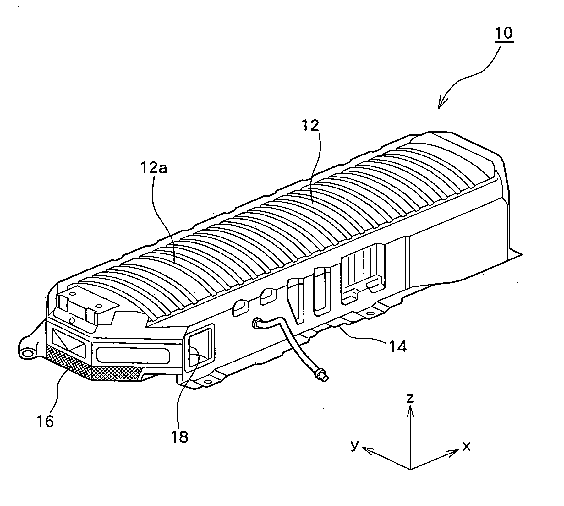
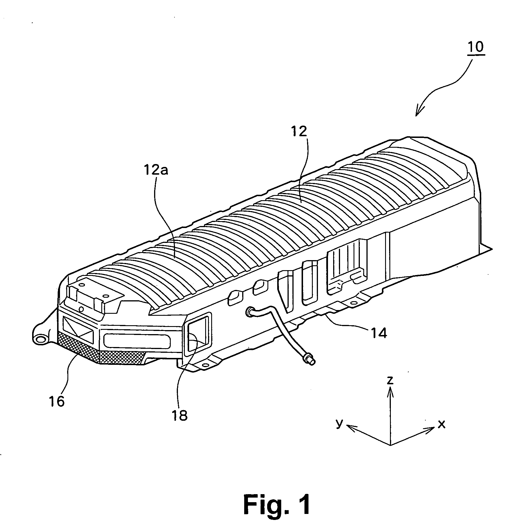
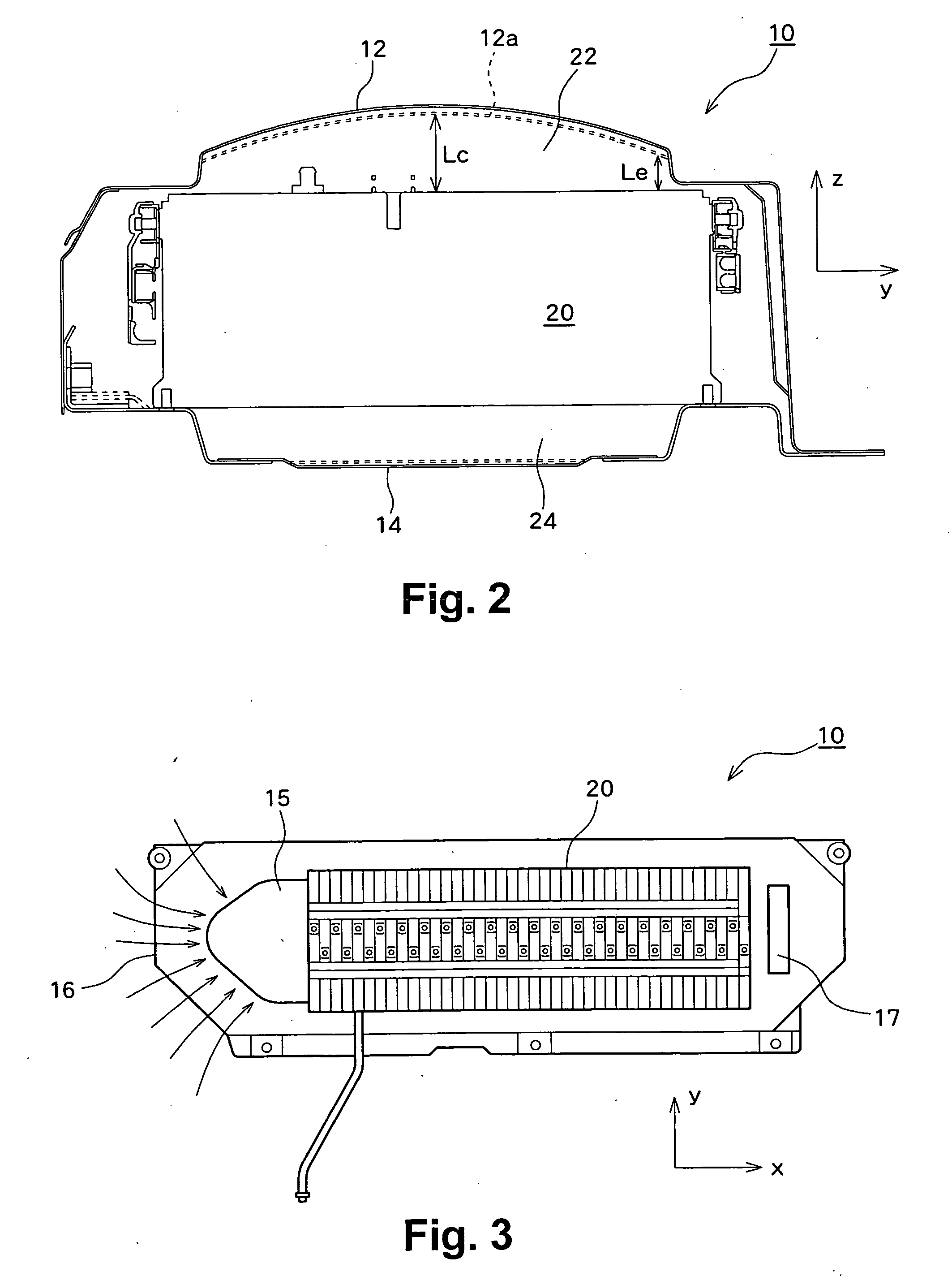
[0022]FIG. 1 is a perspective view showing an external appearance of a battery pack (vehicle power supply) 10 according to the embodiment of the present invention. A battery case serving as a housing for the battery pack 10 has an upper case 12 for covering an upper portion of a built-in battery stack 20 and a lower case 14 for covering a lower portion of the battery stack 20. The battery pack 10 has a battery assembly (battery stack 20) built therein, wherein a plurality of battery modules including one or more single cells, such as nickel-metal hydride batteries or the like, are arranged in parallel (stacked) with a cooling passage interposed therebetween, the battery modules are assembled by restraining end components arranged at their both ends, and the battery modules are electrically connected in series to each other. Further, a cooling fan 15 is provided in the battery pack 1...


PUM


Abstract

A battery pack has a battery stack built therein. A case for the battery pack includes an upper case and a lower case. The upper case is not flat, but forms an arch shape having a curved surface. The upper case has a chamber space formed above the built-in battery stack, and cooling air taken in through an air intake port is supplied to the chamber space. The upper case formed in the shape of an arch prevents deformation of the chamber space against a load applied from above, and adjusts the cooling properties of the battery stack.

Description

[0001] This application claims priority to Japanese Patent Application No. 2005-366900, filed on Dec. 20, 2005, which is incorporated herein by reference in its entirety. BACKGROUND OF THE INVENTION [0002] 1. Field of the Invention [0003] The present invention relates to a housing structure for a battery pack, and, in particular, relates to the housing structure for the battery pack to be mounted on a vehicle. [0004] 2. Description of the Related Art [0005] Conventionally, battery packs for storing power to be supplied to a driving motor (vehicle power supplies) are mounted on hybrid electric vehicles, fuel cell vehicles, or electric vehicles. Battery packs each have an upper case and a lower case for protecting an internal battery stack, and the upper case is provided with a reinforcing structure, such as the structure in which beads are formed in the shape of grooves or the like. [0006] Japanese Patent Laid-Open Publication No. 2005-302590 describes a structure wherein a battery p...

Claims


Application Information

Patent Timeline
IPC IPC(8): H01M2/10B60R16/04H01M10/60H01M10/613H01M10/617H01M10/625H01M10/647H01M10/651H01M10/6563H01M50/209H01M50/244H01M50/249H01M50/271
CPCB60L11/1874B60L11/1877B60L11/1879B60R16/04H01M2/1083H01M10/5004H01M10/5016H01M10/5067H01M10/5073Y02T10/7005Y02T10/705H01M10/625H01M10/6563H01M10/6566H01M10/613B60L58/26B60L50/66B60L50/64Y02T10/70Y02E60/10H01M50/249H01M50/209H01M50/244H01M50/271
Inventor MARUKAWA, SHUHEIETO, TOYOHIKOMISU, MASAHIRO
Owner PANASONIC EV ENERGY CO LTD
Why Eureka
Try Eureka