Battery pack

a battery pack and battery technology, applied in the direction of battery/fuel cell control arrangement, cell components, propulsion by batteries/cells, etc., can solve the problems of anomalous sound, easy reduction of the area of the louver through which the cooling air flows,

Active Publication Date: 2007-06-21
PANASONIC EV ENERGY CO LTD
View PDF4 Cites 17 Cited by
  • Summary
  • Abstract
  • Description
  • Claims
  • Application Information

AI Technical Summary

Benefits of technology

[0009] The present invention provides a battery pack capable of ensuring a flow rate of a medium even when an extraneous matter intrusion prevention member, such as a louver or the like, is provided.

Problems solved by technology

Moreover, an area of the louver through which the cooling air flows is susceptible to a reduction in cross section.
As a result, the flow rate of the cooling air increases, to thus generate an anomalous sound.

Method used


Image

  • Battery pack
  • Battery pack
  • Battery pack

Examples


Embodiment Construction

[0030] An embodiment of the present invention will be described hereinbelow by reference to the drawings.

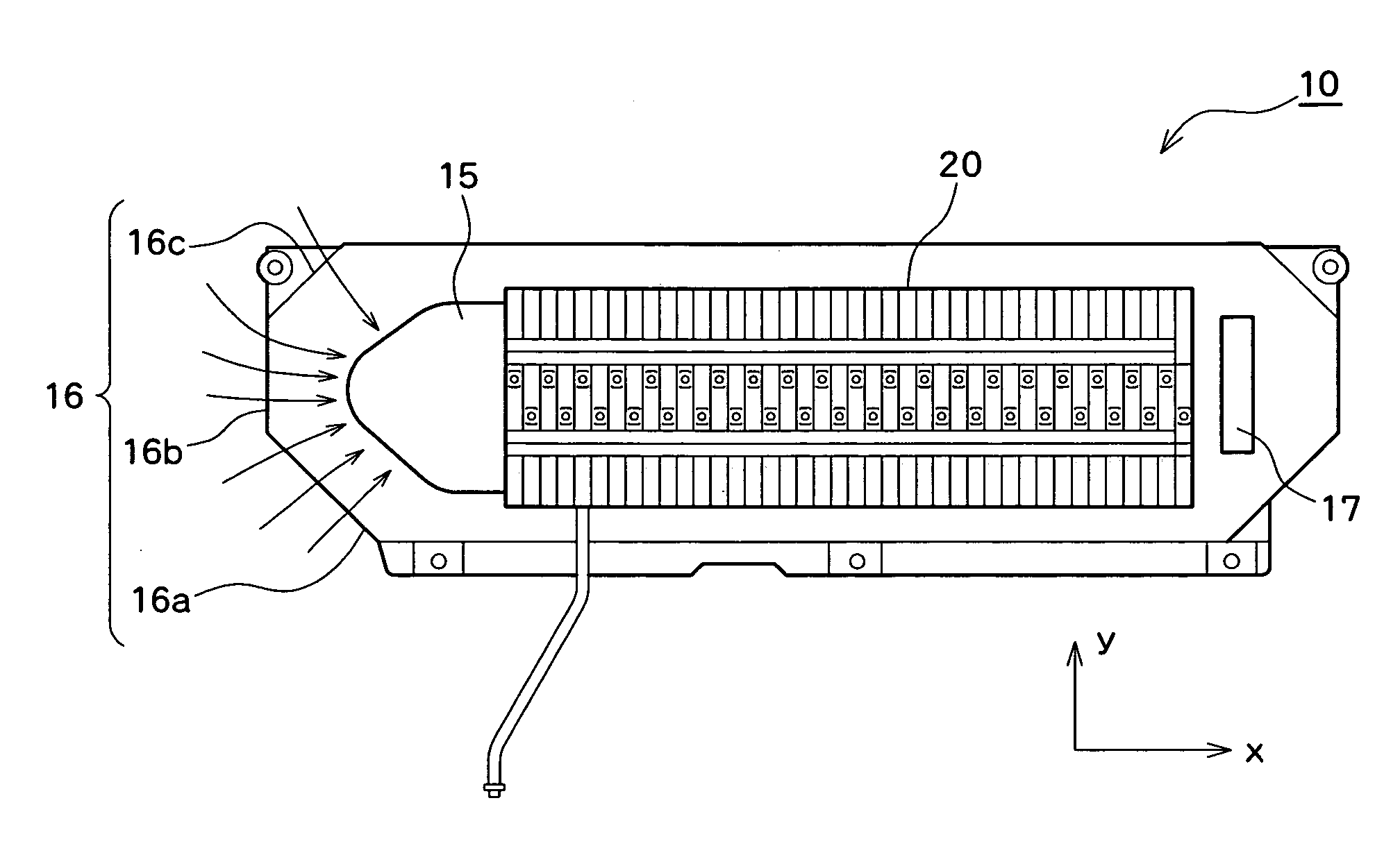
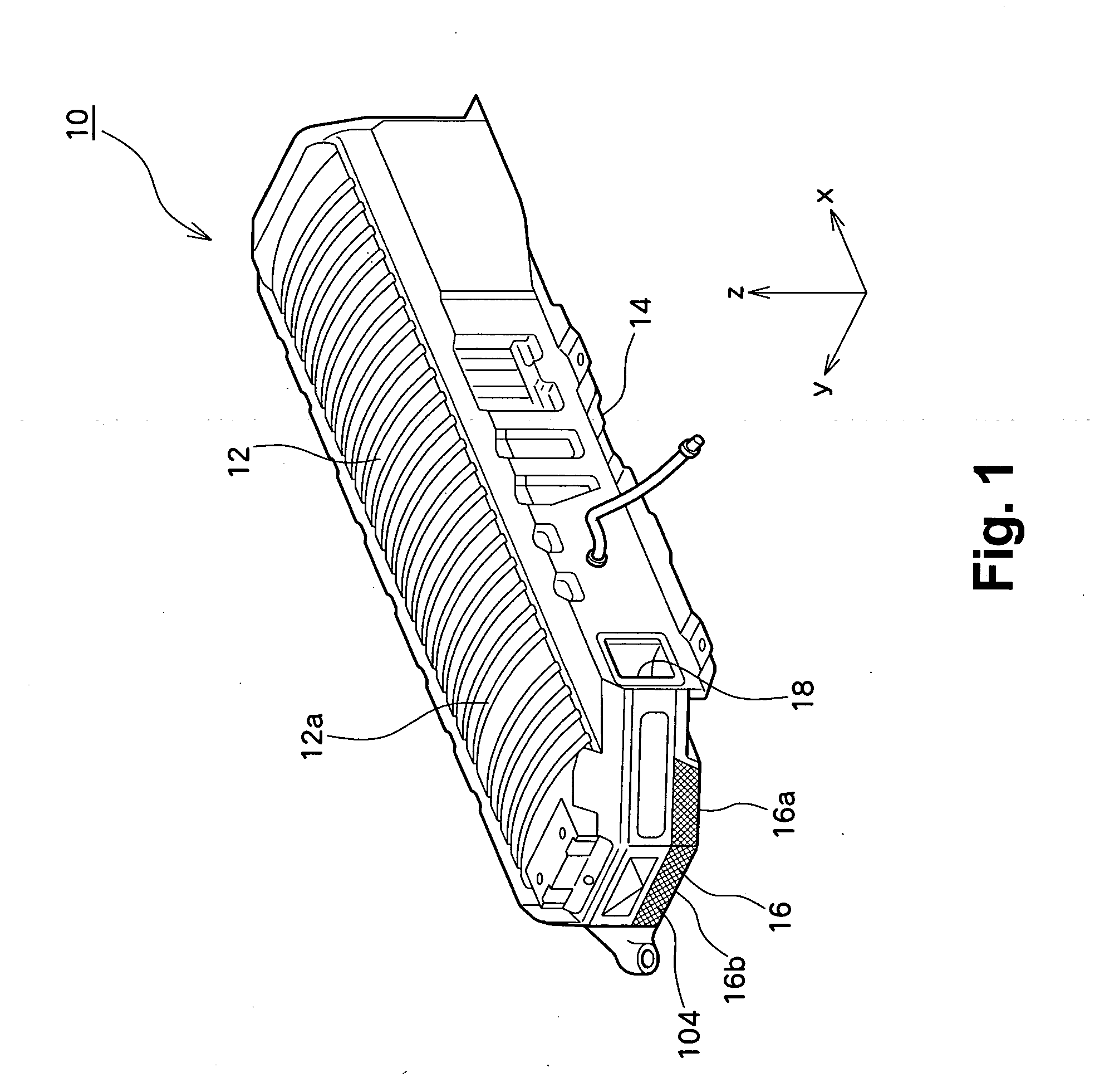
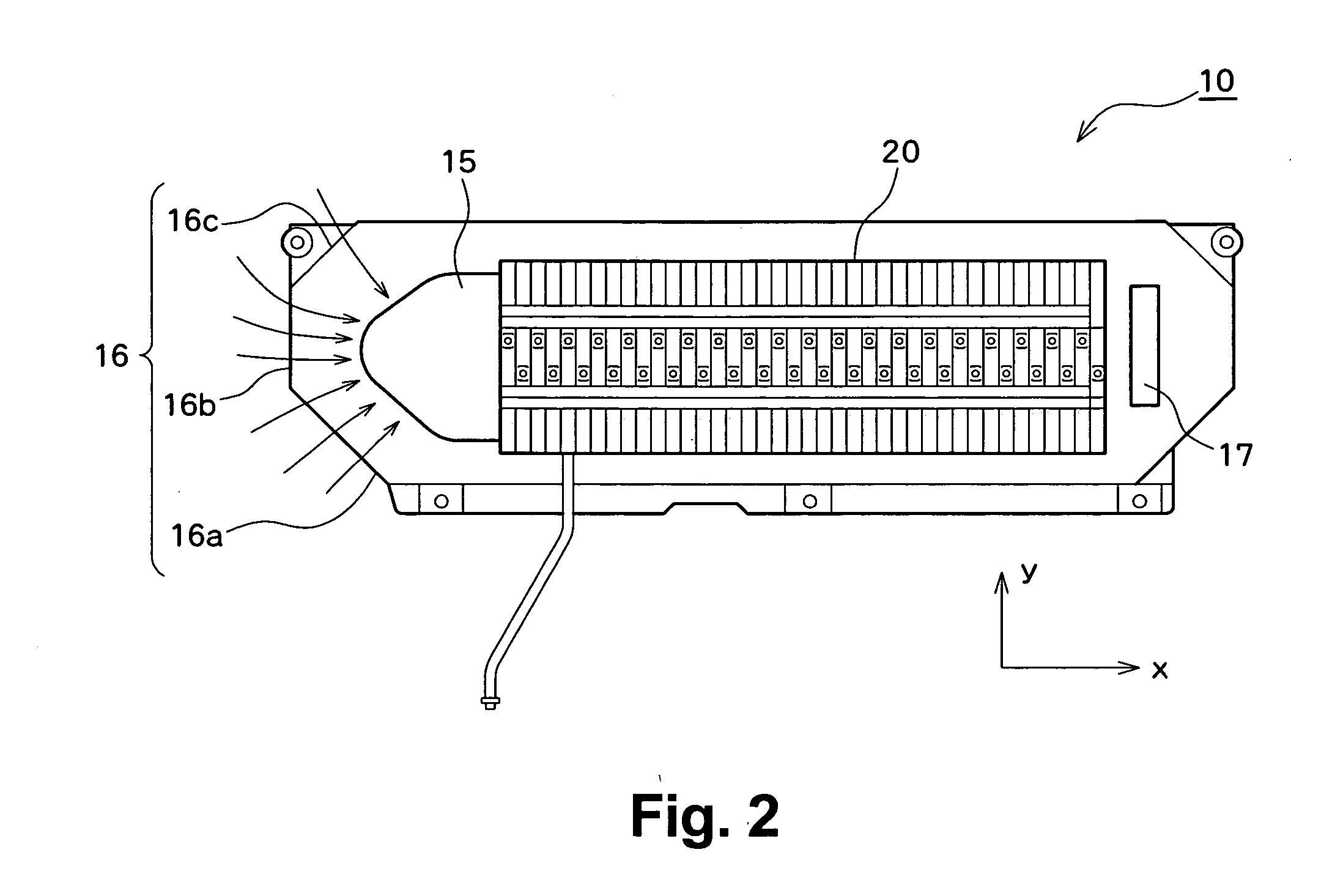
[0031]FIG. 1 is an external perspective view of a battery pack 10 of the present embodiment. A battery case, which is an enclosure of the battery pack 10, has an upper case 12 for covering an upper portion of a battery stack and a lower case 14 for covering a lower portion of the same. The battery pack 10 has a built-in battery assembly (a battery stack). A plurality of battery modules, each formed from one or a plurality of cells such as a nickel-metal hydride battery or the like, are arranged (stacked) in parallel while a cooling passage is routed among the battery modules. End members provided at the respective ends of the cooling passage are assembled in a tied manner, to thus incorporate a battery assembly where battery modules are electrically connected in series with each other. Moreover, a cooling fan is disposed in the battery pack 10. An air intake 16 is formed in one ...


PUM

PropertyMeasurementUnit
temperatureaaaaaaaaaa
structureaaaaaaaaaa
poweraaaaaaaaaa

Abstract

A battery pack to be mounted in a vehicle incorporates a battery stack and a cooling fan. An air intake is formed in a side face located in the vicinity of the cooling fan. In consideration of passengers entering and exiting the vehicle, the air intake is formed as well in a plane generated as a result of removal of a corner. A louver for preventing intrusion of extraneous matter is disposed at the front of the air intake. A decrease in the amount of cooling air induced by the louver is lessened by means of forming the air intake in the plane.

Description

PRIORITY INFORMATION [0001] This application claims priority to Japanese Patent Application No. 2005-366902 filed on Dec. 20, 2005, which is incorporated herein by reference in its entirety. BACKGROUND OF THE INVENTION [0002] 1. Field of the Invention [0003] The present invention relates to a battery pack, and more particularly, to the structure of an air intake of a battery pack mounted in a vehicle. [0004] 2. Related Art [0005] A battery pack is mounted on a hybrid electric vehicle, a fuel-cell-powered vehicle, or an electric vehicle for storing electric power to be supplied to a drive motor. A battery pack has a battery stack, and an equipment box into which various pieces of equipment used for controlling the battery stack are to be incorporated. [0006]FIG. 6 shows an external perspective view of a related-art battery pack 100. The battery pack 100 has a battery stack and various types of devices used for controlling the battery stack. The battery stack is incorporated in a firs...

Claims


Application Information

Patent Timeline
Patent Type & Authority Applications(United States)
IPC IPC(8): H01M10/50H01M2/12B60R16/04H01M10/60H01M10/613H01M10/625H01M10/647H01M10/651H01M10/6563H01M50/209H01M50/249H01M50/271
CPCB60L11/1874B60L11/1879H01M2/1083H01M10/5004H01M10/5016H01M10/5067H01M10/5073Y02T10/7005Y02T10/705H01M10/625H01M10/6563H01M10/6566H01M10/613B60L58/26B60L50/64Y02T10/70Y02E60/10H01M50/249H01M50/209H01M50/271
Inventor MARUKAWA, SHUHEIETO, TOYOHIKOMISU, MASAHIRO
Owner PANASONIC EV ENERGY CO LTD
Why Eureka
Try Eureka