
Tissue sample needle and method of using same

a needle and tissue technology, applied in the field of tissue sample needles, can solve the problems of affecting the extraction efficiency of soft tissue, the inability of devices to reliably extract soft tissue, and the tearing of tissue, and achieve the effect of reducing the diameter of the inner tub

Inactive Publication Date: 2007-06-21
RANFAC
View PDF76 Cites 65 Cited by
  • Summary
  • Abstract
  • Description
  • Claims
  • Application Information

AI Technical Summary

Benefits of technology

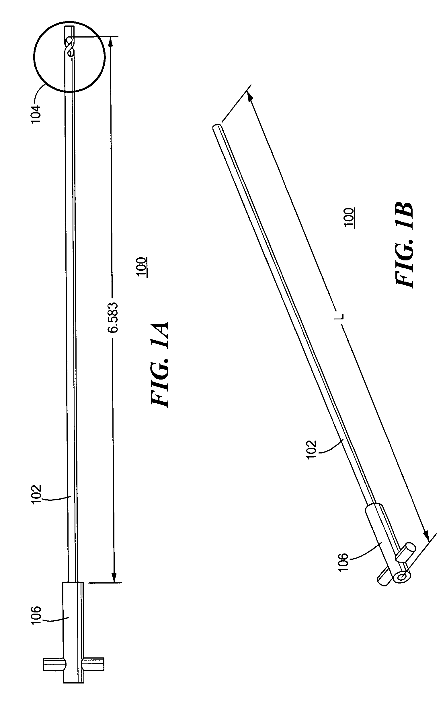
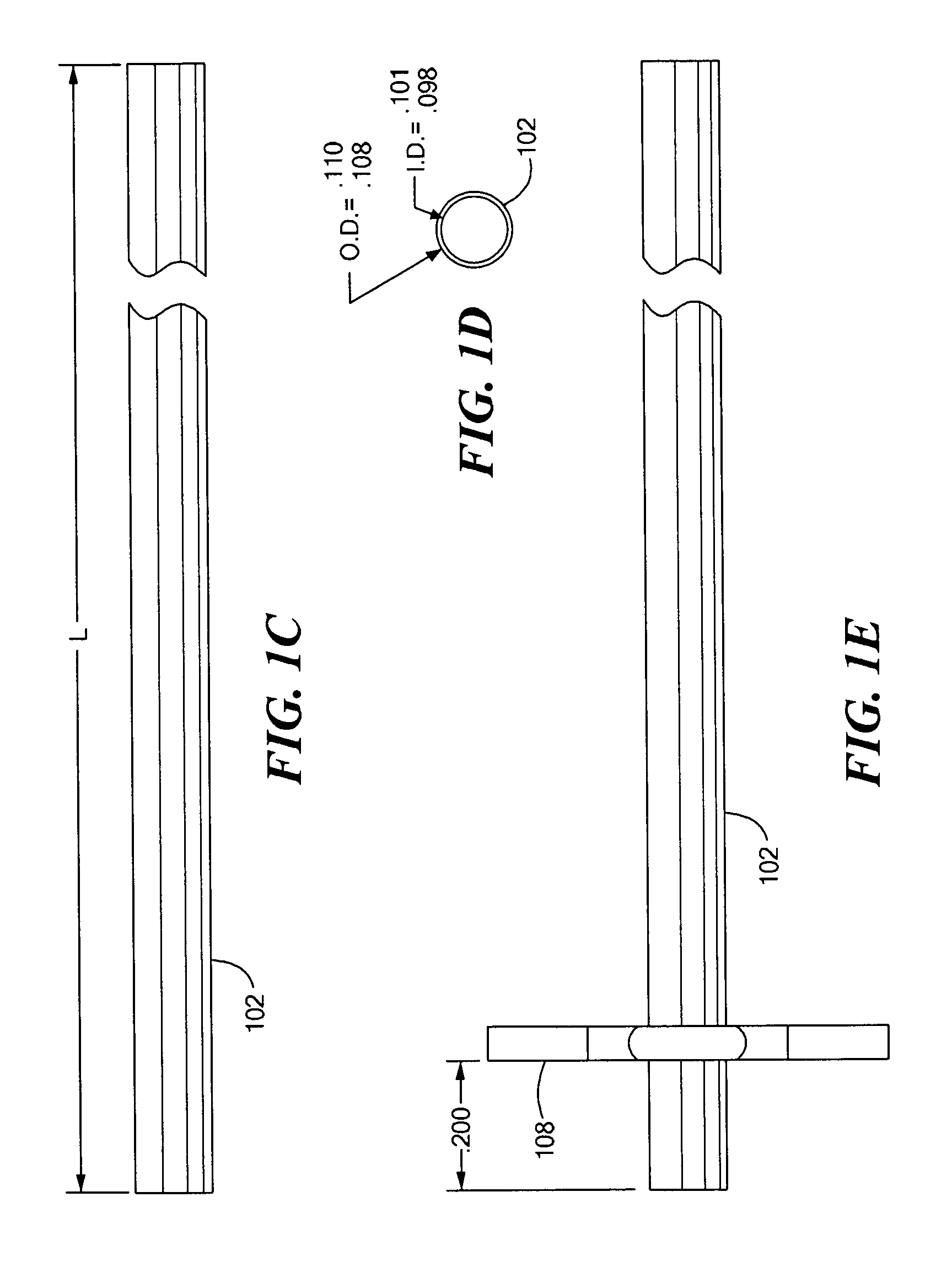
[0004] In accordance with one aspect of the invention there is provided a tissue sample needle comprising an outer tube having a proximal end and a distal end and an inner tube disposed within the outer tube, the inner tube comprising a tube body constituting a proximal end of the inner tube, a securing member constituting a distal end of the inner tube and coupled to the outer tube at the distal end of the outer tube, and a snare having a plurality of deformable members respectively coupled at a first end to the securing member and at a second end to the tube body. The plurality of deformable members are configured to deform inward upon rotation of the tube body relative to the securing member and the outer tube so as to effectively reduce the diameter of the inner tube within a zone of deformation for obtaining a tissue sample within the tube body.
[0006] In accordance with another aspect of the invention there is provided an inner tube for a tissue sample needle. The inner tube includes a tube body constituting a proximal end of the inner tube; a securing member constituting a distal end of the inner tube; and a snare having a plurality of deformable members respectively coupled at a first end to the securing member and at a second end to the tube body. The plurality of deformable members are configured to deform inward upon rotation of the tube body relative to the securing member so as to effectively reduce the diameter of the inner tube within a zone of deformation for obtaining a tissue sample within the tube body.
[0008] In accordance with another aspect of the invention there is provided an inner tube for a tissue sample needle having an inner tube and an outer support structure, the inner tube comprising a tubular body constituting a proximal end of the inner tube and a plurality of deformable members respectively coupled at a first end to a support structure and at a second end to the tubular body. The plurality of deformable members configured to deform upon rotation of the tube body relative to the support structure so as to effectively reduce the diameter of the inner tube within a zone of deformation.
[0012] In accordance with another aspect of the invention there is provided a method of obtaining a tissue sample. The method involves inserting a tissue sample needle into a body organ, the tissue sample needle including an outer tube having a proximal end and a distal end and an inner tube disposed within the outer tube, the inner tube comprising a tube body constituting a proximal end of the inner tube, a securing member constituting a distal end of the inner tube and coupled to the outer tube at the distal end of the outer tube, and a snare having a plurality of deformable members respectively coupled at a first end to the securing member and at a second end to the tube body, the plurality of deformable members configured to deform inward upon rotation of the tube body relative to the securing member and the outer tube so as to effectively reduce the diameter of the inner tube within a zone of deformation; and actuating the needle by rotating the inner tube relative to the securing member and the outer tube.

Problems solved by technology

The constricting action of such a device does not necessarily cut the tissue since the snare does constrict to zero diameter, but rather the tissue is often ripped upon rearward motion of the needle.
For example, such a device would generally be unreliable in extracting soft tissue such as that which might be extracted in a breast biopsy.

Method used


Image

  • Tissue sample needle and method of using same
  • Tissue sample needle and method of using same
  • Tissue sample needle and method of using same

Examples


Embodiment Construction

[0047] In embodiments of the present invention, a tissue sample needle includes a snare designed to efficiently pinch or sever tissue or tissue-like material upon actuation of the snare with a twisting action. The snare is typically tubular in shape and may be integral to the inner tube of the tissue sample needle. The snare is effective on soft tissue as well as harder tissue such as bone marrow. Efficient pinching or severing of tissue is achieved by a deformable zone of the snare having two or more deformable members that deform inwardly upon actuation. Some or all of the deformable members may contact other deformable members upon twisting in one direction to effectively reduce the inner diameter of the snare to zero. Twisting in the opposite direction will typically expand the diameter of the tube and allow the tissue to be recovered. The deformable members may be helical or serpentine in shape. There may be two, three, four, five, six, seven, or even more deformable members. T...


PUM


Abstract

A tissue sample needle having an outer tube and an inner tube disposed within the outer tube, the inner tube having a distal end that is provided with a snare having a plurality of deformable members extending from the inner tube. The free ends of the members are coupled directly or indirectly to the outer tube. Upon rotation of the inner tube with respect to the outer tube, the members deflect inward to reduce the effective diameter of the inner tube in the deflection zone to sever and / or hold a biopsy piece within the inner tube. After removal of the needle from a body tissue, rotating the inner tube in the opposite direction causes the members to return substantially to their original positions and thereby return the inner tube substantially to its original diameter and allow the biopsy piece to be removed or ejected from the needle.

Description

FIELD OF THE INVENTION [0001] The present invention relates to devices and methods for the removal of tissue samples from a body organ. BACKGROUND OF THE INVENTION [0002] In the practice of medical diagnostics, it is often necessary to perform a biopsy to remove sample of the patient's tissue for pathological study. Various devices are known in the art that are intended to make the biopsy procedure faster, more reliable, easier to perform and reduces the chance of discomfort or injury to the patient. [0003] Certain biopsy needle devices are disclosed in the following United States patents, all of which are hereby incorporated herein by reference in their entireties: U.S. Pat. No. 5,522,398 issued on Jun. 4, 1996 to Goldenberg et al. and assigned to Medsol Corporation; U.S. Pat. No. 5,634,473 issued on Jun. 3, 1997 to Goldenberg et al. and assigned to Medsol Corporation; U.S. Pat. No. 5,843,001 issued on Dec. 1, 1998 to Goldenberg; U.S. Pat. No. 6,015,391 issued on Jan. 18, 2000 to R...

Claims


Application Information

Patent Timeline
IPC IPC(8): A61B10/00
CPCA61B10/0266A61B10/0275
Inventor PROVENCHER, KEVIN M.
Owner RANFAC
Learn More