Heat exchanger and washing apparatus comprising the same
- Summary
- Abstract
- Description
- Claims
- Application Information
AI Technical Summary
Benefits of technology
Problems solved by technology
Method used
Image
Examples
tenth embodiment
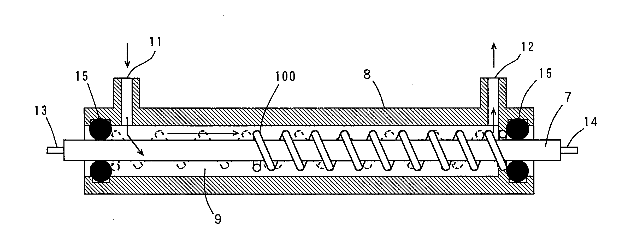
[0288]FIG. 14 is a cross-sectional view in the axial direction of a heat exchanger in a tenth embodiment of the present invention. The heat exchanger according to the tenth embodiment differs from the heat exchanger according to the third embodiment in that a plurality of spiral springs 102, 103, and 104 are provided so as not to come into direct contact with an outer peripheral surface of a sheathed heater 7 and an inner peripheral surface of a case 8 and in that a plurality of spring supporting stands 21 for supporting the springs 102, 103, and 104 such that respective ends of the springs 102, 103, and 104 do not come into contact with the inner peripheral surface of the case 8. Also in this case, spiral flow paths 9c, 9e, and 9g are intermittently formed within the case 8, and cylindrical flow paths 9d and 9f are formed thereamong. The springs 102, 103, and 104 function as a flow velocity conversion mechanism, a flow direction conversion mechanism, a turbulent flow generation mec...
eleventh embodiment
[0291]FIG. 15 is a cross-sectional view in the axial direction of a heat exchanger in an eleventh embodiment of the present invention. The heat exchanger according to the eleventh embodiment differs from the heat exchanger according to the ninth embodiment in that a spiral spring 105 is provided in a region RA where the surface temperature of a copper pipe 17 in a sheathed heater 7 becomes not less than a predetermined temperature. The region RA is a region centered on the slightly downward side from the center of the copper pipe 17. In this case, a spiral flow path 9b is formed around the region RA where the surface temperature of the copper pipe 17 within a case 8 becomes not less than a predetermined temperature, and a cylindrical flow path 9a is formed around the other region. The spring 105 functions as a flow velocity conversion mechanism, a flow direction conversion mechanism, a turbulent flow generation mechanism, and an impurity removal mechanism.
[0292] The operation and t...
twelfth embodiment
[0296]FIG. 16 is a cross-sectional view in the axial direction of a heat exchanger in a twelfth embodiment of the present invention. The heat exchanger according to the twelfth embodiment differs from the heat exchanger according to the eleventh embodiment in that a spiral spring 106 is provided in the vicinity of and on the upstream side of a region RA where the surface temperature of a copper pipe 17 in a sheathed heater 7 becomes not less than a predetermined temperature. The region RA is a region centered on the slightly downward side from the center of the copper pipe 17. In this case, a cylindrical flow path 9a is formed around the region RA where the surface temperature of the copper pipe 17 within a case 8 becomes not less than the predetermined temperature, and a spiral flow path 9b is formed in the vicinity of and on the upstream side of the region RA. The spring 106 functions as a flow velocity conversion mechanism, a flow direction conversion mechanism, a turbulent flow ...
PUM
 Abstract
Description
Claims
Application Information
 - R&D
- Intellectual Property
- Life Sciences
- Materials
- Tech Scout
- Unparalleled Data Quality
- Higher Quality Content
- 60% Fewer Hallucinations
Browse by: Latest US Patents, China's latest patents, Technical Efficacy Thesaurus, Application Domain, Technology Topic, Popular Technical Reports.
© 2025 PatSnap. All rights reserved.Legal|Privacy policy|Modern Slavery Act Transparency Statement|Sitemap|About US| Contact US: help@patsnap.com


