Handle with vibration-reducing device

a technology of vibration reduction device and handle, which is applied in the field of handles, can solve the problems of achieving a relatively small maximum torque and achieve the effect of reducing the disadvantages of the handle and achieving a larger torque transmission

Inactive Publication Date: 2007-06-28
HILTI AG
View PDF6 Cites 30 Cited by
  • Summary
  • Abstract
  • Description
  • Claims
  • Application Information

AI Technical Summary

Benefits of technology

[0007] The object of the invention is to eliminate the aforesaid disadvantages of the ha

Problems solved by technology

A disadvantage of the known side handle consists in that upon tightening or loosening the screw connection, a relatively small maximum torque can be

Method used


Image

  • Handle with vibration-reducing device
  • Handle with vibration-reducing device
  • Handle with vibration-reducing device

Examples


Embodiment Construction

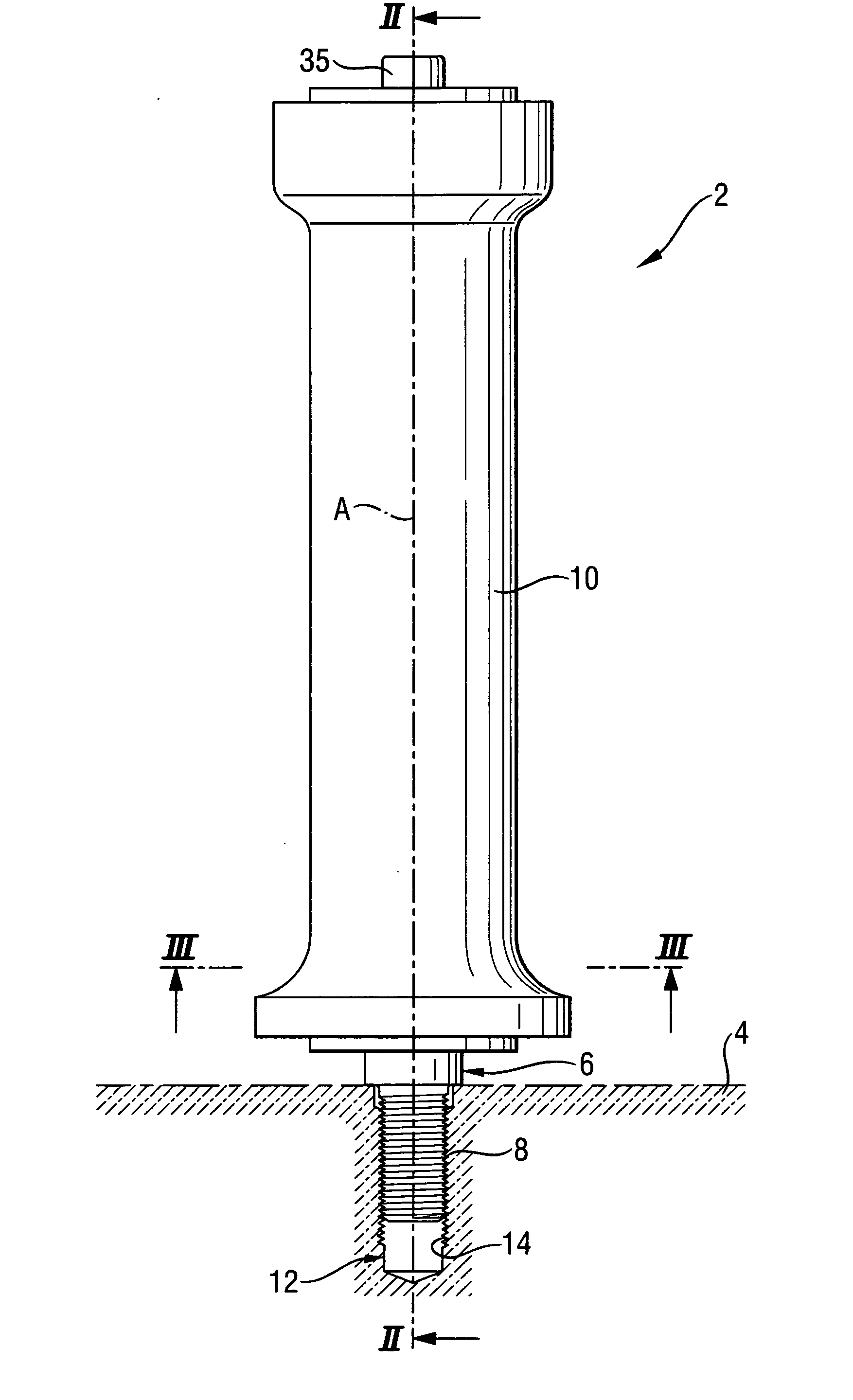
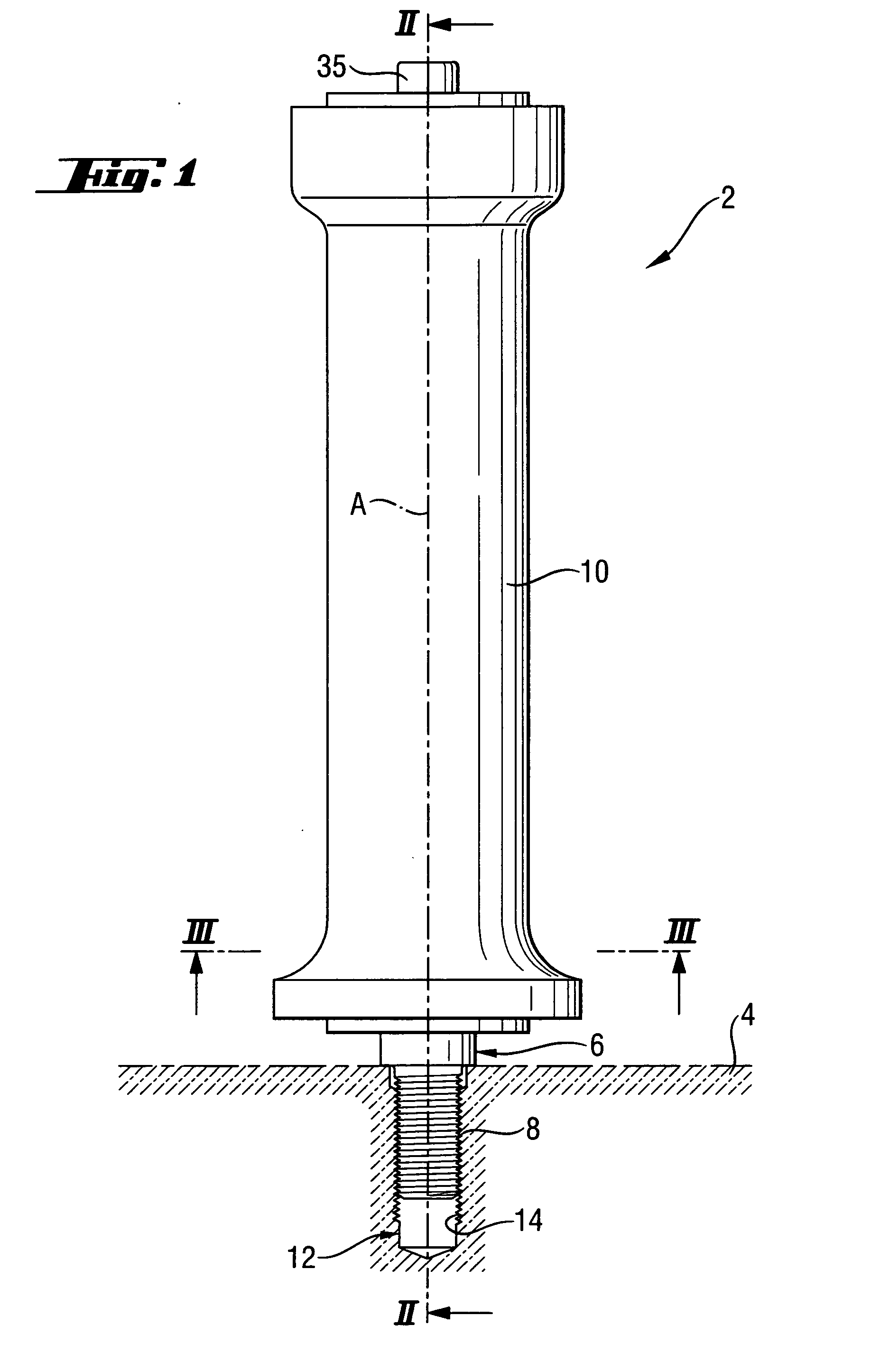
[0029]FIG. 1 shows a handle 2 in the form of a side handle, which is to be attached to an angle grinder, a drilling hammer, or a chisel hammer. For this purpose, the handle 2 has attachment means 6, which includes a thread 8 in the form of an external thread, and which is connected with the outer sleeve 10. Further, the outer sleeve 10 and the thread 8 extend along a common longitudinal axis A.

[0030] The pivot attachment means 6 is connectable with the counter-attachment means 12, which includes a counter thread 14 in the form of an internal thread provided in the hand-held power tool 4. Alternatively, the pivot attachment means 6 can also comprise commercially available clamp band means, which can be mounted on a corresponding receiving area of the hand-held power tool (not shown).

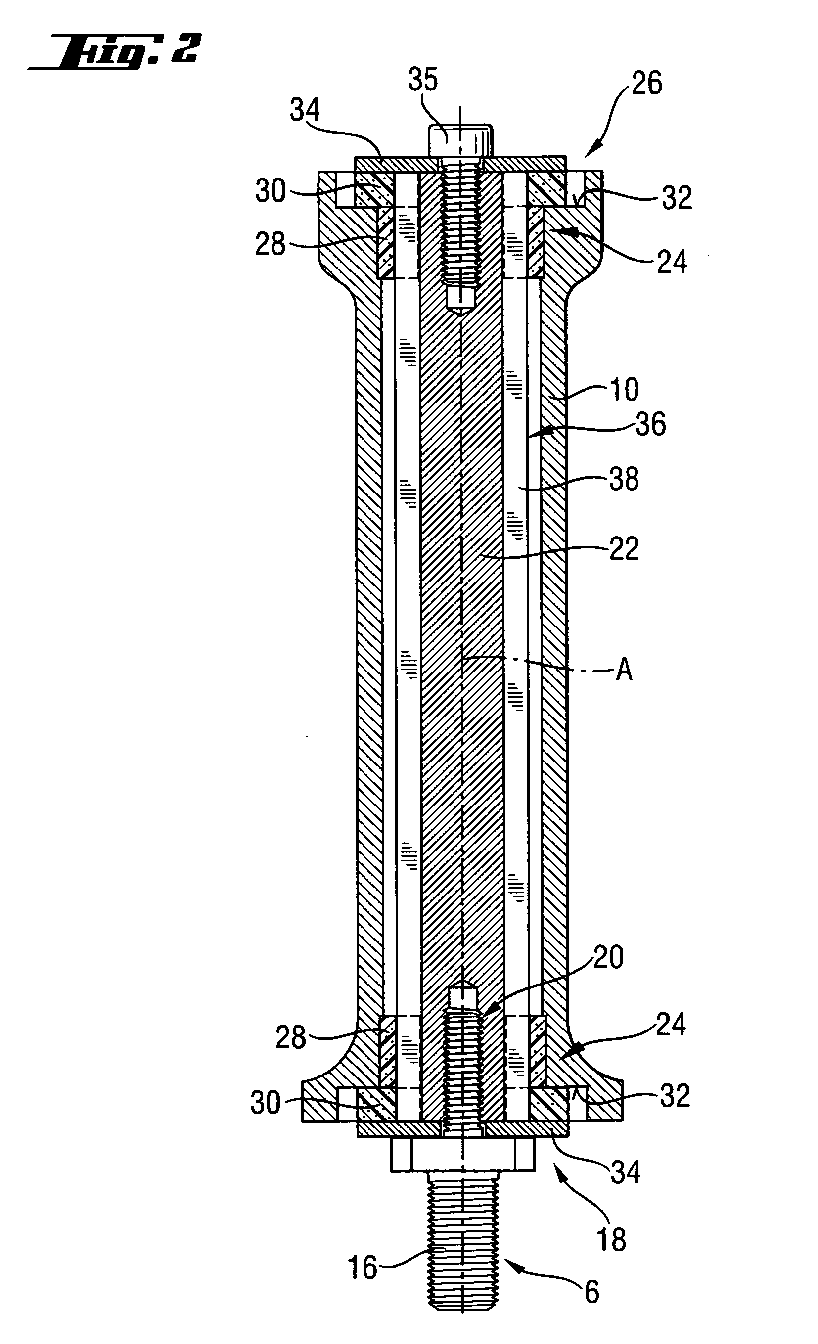
[0031] As indicated in FIG. 2, the pivot attachment means 6 is formed at an end piece 16, which is connected to the first end of the handle 2 facing the hand-held power tool 4 via a screw connection 20 ...


PUM


Abstract

A handle (2) of a hand-held power tool (4), includes an outer sleeve (10) to be gripped by a user, a support element (22) extending at least partially within the outer sleeve (10) along a longitudinal axis (A), a pivot attachment element (6) which at least partially is rotatable with the support element (22) and can be fixed via the handle (2) on the hand-held power tool (4), an elastic vibration-reducing device (24) which encompasses support element (22) and holds the outer sleeve (10) in a radially spaced relationship relative to the support element (22) which has an outer profile (36) with radial outer profile elevations (38) which, at least at the axial height of the vibration-reducing device (24), are arranged at a level of the radial inner profile elevations (44) of an inner profile (50) of the outer sleeve (10).

Description

BACKGROUND OF THE INVENTION [0001] 1. Field of the Invention [0002] The invention relates to a handle for use on a vibration-generating hand-held power tool, such as an angular grinder, drilling hammer, or chisel hammer. The device includes an outer sleeve to be gripped by a user and a support element, which at least partially extends inside the outer sleeve along a longitudinal axis. The support element is connected with pivot means for joint rotation therewith. The pivot means can include, for example, thread means or parts of a clamp band means. With the thread means or the clamp band means, the handle can be connected by applying torque thereto with a hand-held power tool, which, for example, has a corresponding counter-thread means or receiving surface for the clamp band means. Further, the handle comprises an elastic vibration-reducing device enclosing the support element, and with which the outer sleeve is spaced radially from the support element. [0003] 2. Description of the...

Claims


Application Information

Patent Timeline
IPC IPC(8): B25G3/32
CPCB25F5/006Y10T16/469B25F5/026
Inventor FISCHER, AXEL
Owner HILTI AG
Why Eureka
Try Eureka