Liquid fuel storage system
a fuel storage system and liquid fuel technology, applied in the direction of electrochemical generators, lighting and heating equipment, container discharge methods, etc., can solve the problem of difficult mounting of large-sized fuel storage containers, and achieve the effect of reducing the load of the air conditioning equipmen
- Summary
- Abstract
- Description
- Claims
- Application Information
AI Technical Summary
Benefits of technology
Problems solved by technology
Method used
Image
Examples
first embodiment
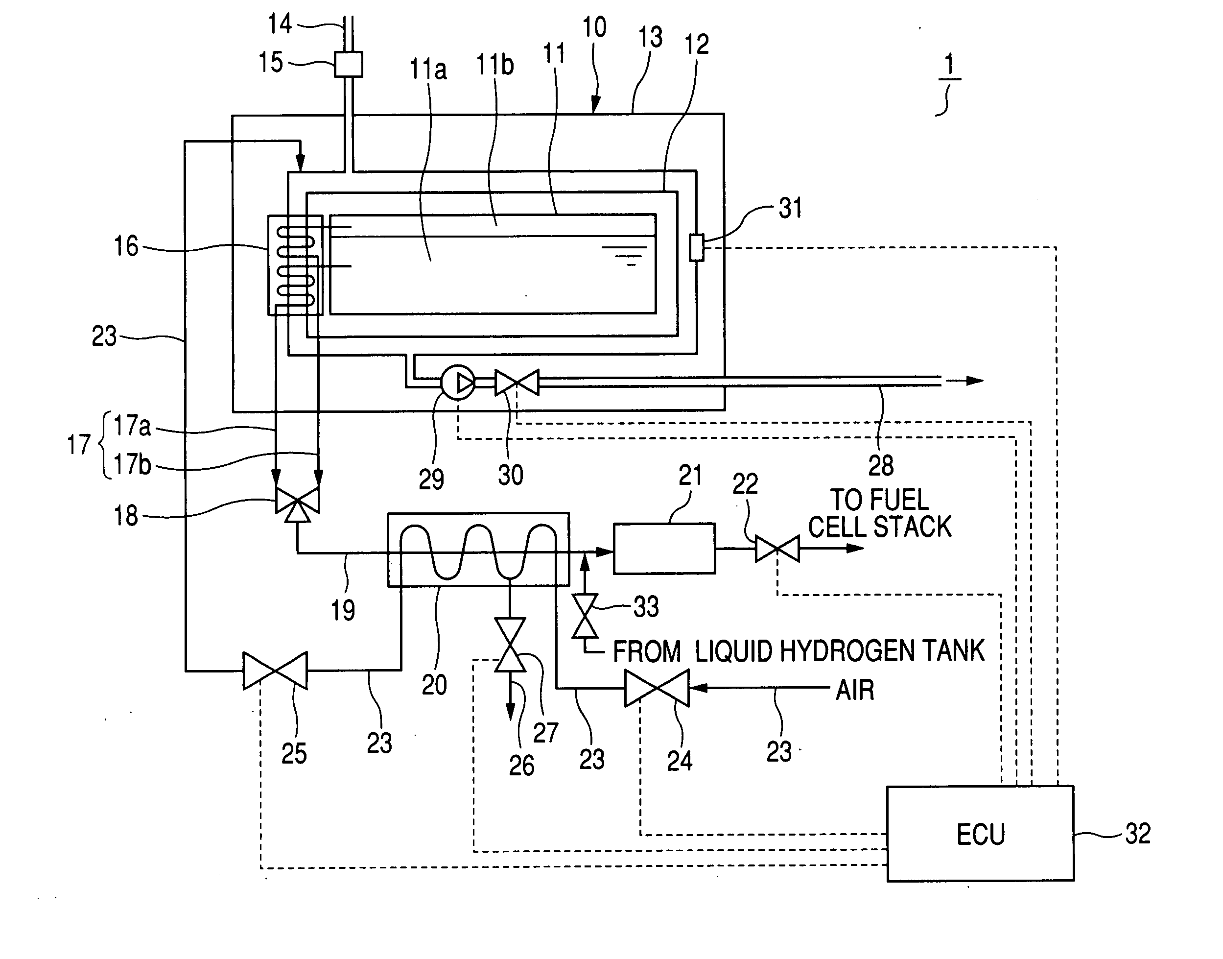
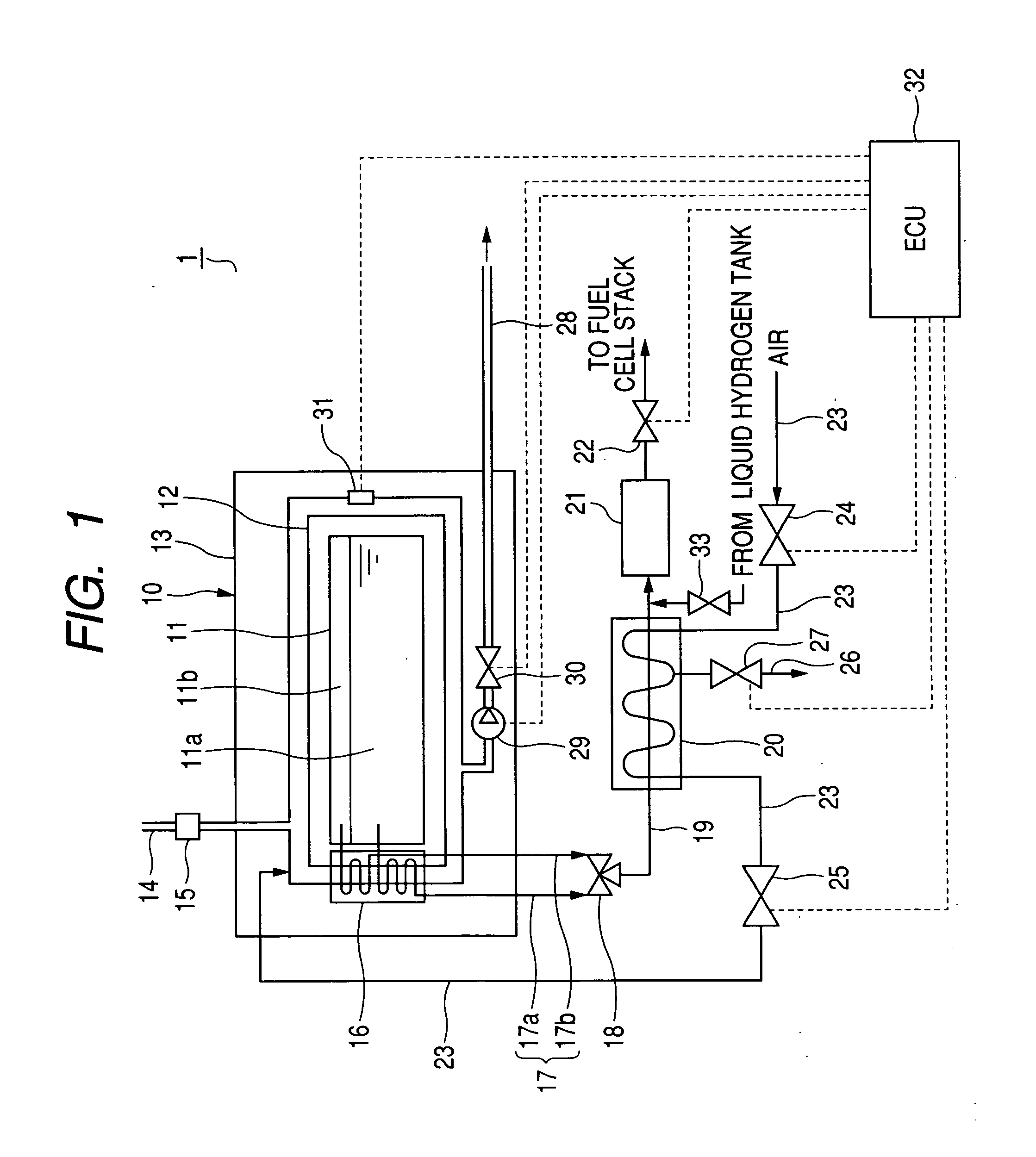
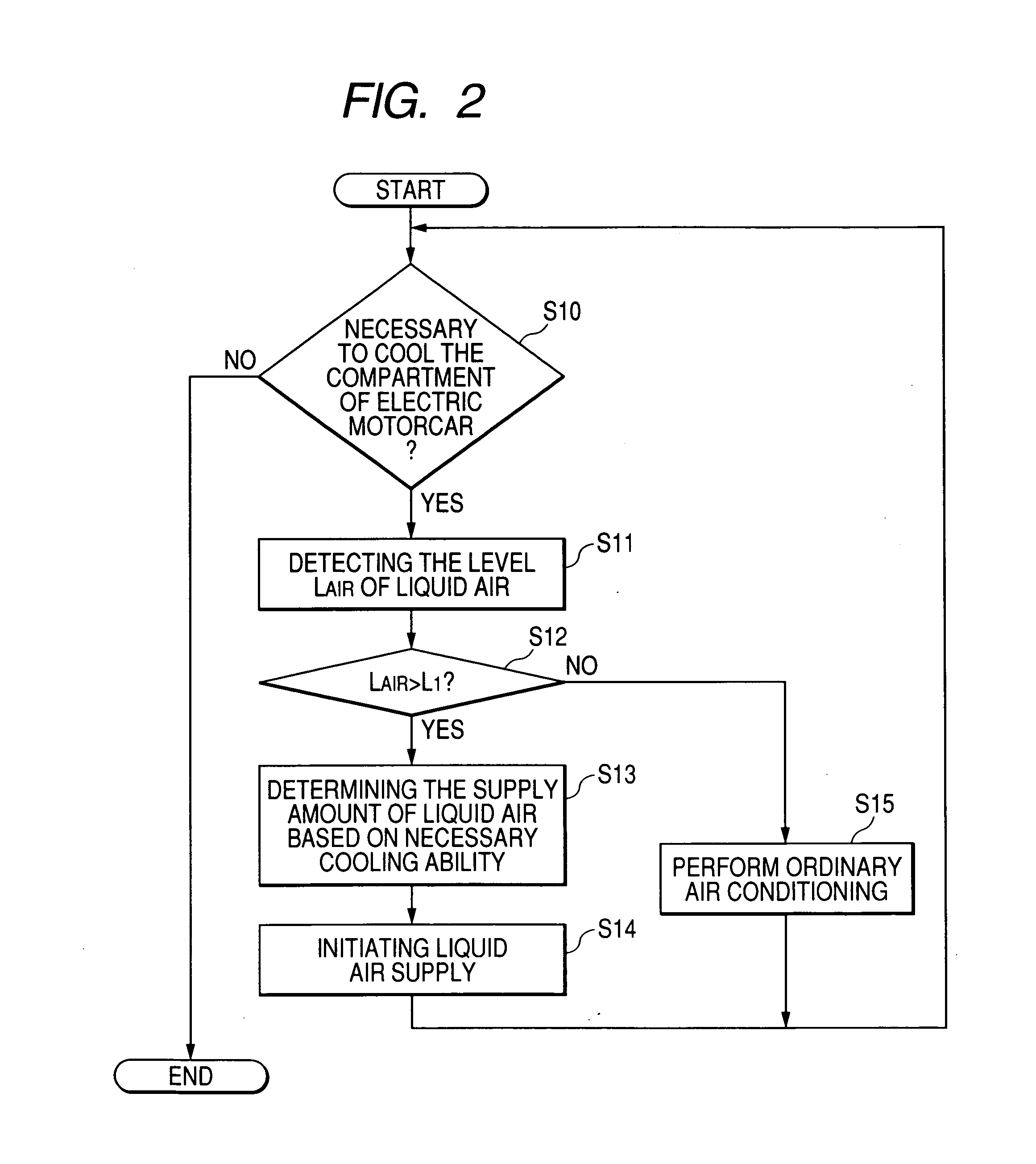
[0023]A description will be given of a liquid fuel storage system 1 equipped with a liquid hydrogen storage container according to the first embodiment with reference to FIG. 1 and FIG. 2.
[0024]In the first embodiment, the concept of the present invention is applied to the liquid fuel storage system 1 equipped with the liquid hydrogen storage container 10 configured to store liquid hydrogen to be supplied to a fuel of a fuel cell stack (omitted from the drawings). Such a liquid hydrogen storage container 10 is to be mounted on vehicles such as an electric motorcar (a fuel cell vehicle) using the fuel cell stack as an electric power source. The electric motorcar is equipped with an air conditioning apparatus for air conditioning of the inside of a compartment of the electric motorcar. The air conditioning apparatus performs a well-known thermal cycle system composed of a vaporizer, a compressor, a condenser, a pressure reduction means, and the like.
[0025]FIG. 1 is a schematic view of...
second embodiment
[0065]A description will be given of a liquid fuel storage system according to the second embodiment with reference to FIG. 3.
[0066]FIG. 3 is a sectional view of a cold container 40 to be mounted on the liquid fuel storage system according to the second embodiment. In particular, FIG. 3 shows only the cold container 40 because other components of the liquid fuel storage system are the same of those of the liquid fuel storage system 1 according to the first embodiment shown in FIG. 1. The explanation of the same components is omitted here.
[0067]The cold container 40 shown in FIG. 3 is capable of maintaining the temperature of a cold room 41 of the cold container 40 for storing materials at a low temperature. The cold container 40 has a multiple-layer construction. Materials such as drinking water are contained in the cold room 41 located at the most inner layer of the cold container 40. An air room 42 is formed at the outer periphery of the cold room 41, that is, the air room 42 surr...
PUM
 Abstract
Description
Claims
Application Information
 - R&D
- Intellectual Property
- Life Sciences
- Materials
- Tech Scout
- Unparalleled Data Quality
- Higher Quality Content
- 60% Fewer Hallucinations
Browse by: Latest US Patents, China's latest patents, Technical Efficacy Thesaurus, Application Domain, Technology Topic, Popular Technical Reports.
© 2025 PatSnap. All rights reserved.Legal|Privacy policy|Modern Slavery Act Transparency Statement|Sitemap|About US| Contact US: help@patsnap.com


