Method for Preparing NC Machining Program and Apparatus for Preparing NC Machining Program

Inactive Publication Date: 2007-06-28
YAMAZAKI MAZAK CORPORATION
View PDF25 Cites 4 Cited by
  • Summary
  • Abstract
  • Description
  • Claims
  • Application Information

AI Technical Summary

Benefits of technology

[0021] An object of the present invention is to provide a method which can easily prepare an NC machining pro

Problems solved by technology

Further, since a part of a rotating force is applied to the bite 50 at a time when the workpiece W is rotated, the bite 50 is bent and the cutting process is not stable.
However, a profile irregularity of the processed surface of the workpiece W is low, and a machining efficiency is low.
However, since the rotating s

Method used


Image

  • Method for Preparing NC Machining Program and Apparatus for Preparing NC Machining Program
  • Method for Preparing NC Machining Program and Apparatus for Preparing NC Machining Program
  • Method for Preparing NC Machining Program and Apparatus for Preparing NC Machining Program

Examples


Example

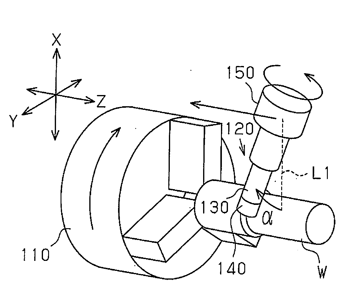
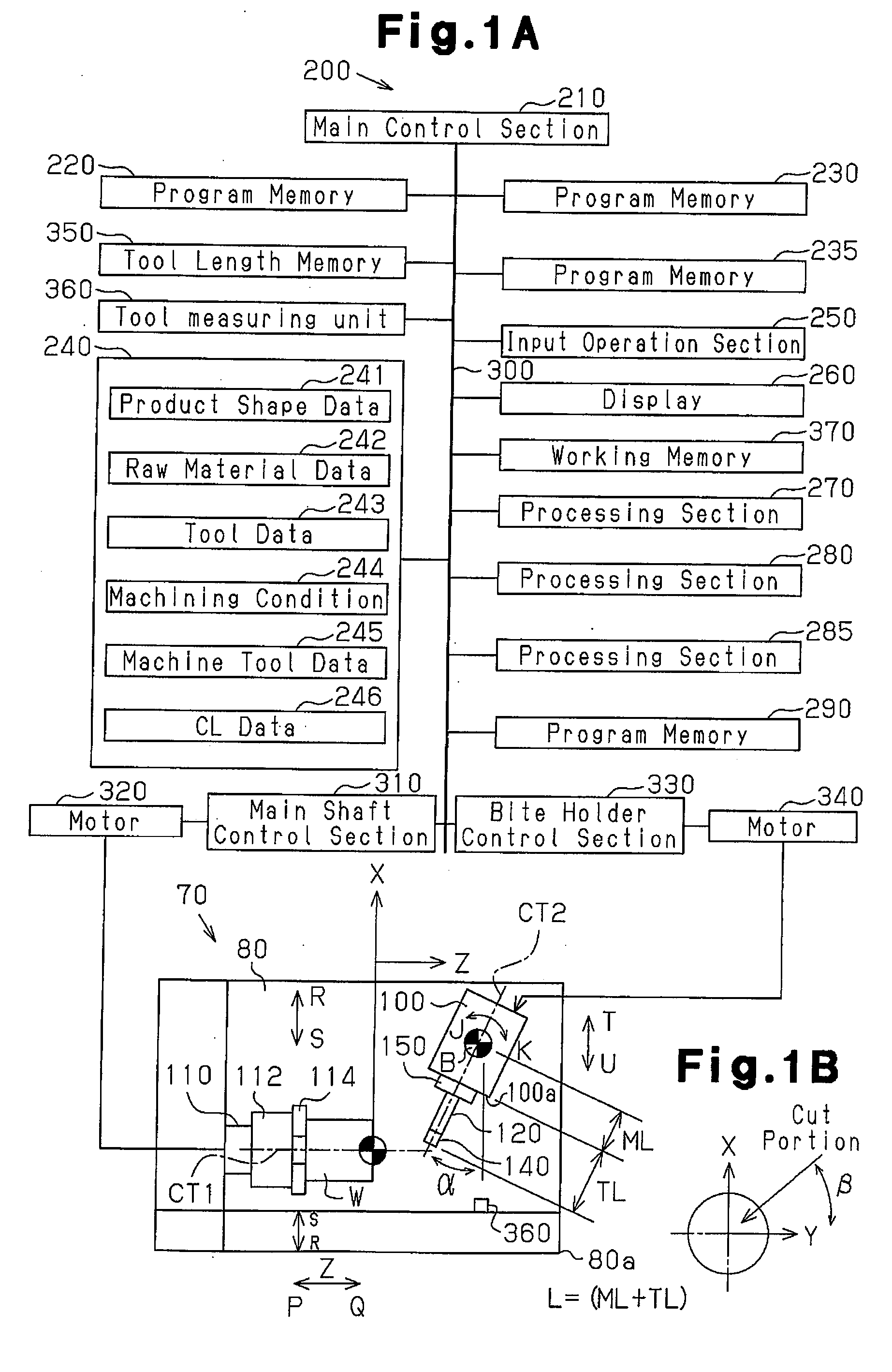
[0039] A description will be given of an embodiment obtained by embodying the present invention in a preparing apparatus of an NC machining program for an NC machining apparatus, with reference to FIGS. 1 to 5.

[0040] As shown in FIG. 1, a preparing apparatus 200 is provided with a main control section 210 constituted by a CPU. To the main control section 210, there are connected various memories 220, 230, 235, 290 and 350, storage means 240, an input operation section 250, a display 260, processing sections 270 and 280, various control sections 310 and 330, a tool measuring unit 360 and the like via a bus line 300. Further, a working memory 370 constituted by a RAM is connected to the main control section 210 via the bus line 300.

[0041] Each of the program memories 220, 230 and 235 is constituted by a ROM. A system program for executing various controls of the preparing apparatus 200 is stored in the program memory 220. A program for preparing the NC machining program is stored in...


PUM

PropertyMeasurementUnit
Dimensionaaaaaaaaaa

Abstract

A preparing apparatus of an NC machining program prepares an NC machining program including a position instruction of a cutting portion of a rotary tool on the basis of a two-dimensional workpiece coordinate system having a Z-axis and an X-axis as coordinate axes. An operator inputs a lead clearance α and a radial clearance β to the preparing apparatus via an input operation section. A processing section converts the NC machining program prepared on the basis of the two-dimensional workpiece coordinate system into an NC machining program including a position instruction of a three-dimensional workpiece coordinate system having the X-axis, a Y-axis and the Z-axis as the coordinate axes, on the basis of the lead clearance α and the radial clearance β.

Description

BACKGROUND OF THE INVENTION [0001] The present invention relates to a method for preparing an NC machining program and an apparatus for preparing an NC machining program. [0002] Conventionally, there has been known an NC machining apparatus for executing a cutting process of a workpiece made of a difficult-to-machine material such as a heat-resistant alloy or the like. As the NC machining apparatus, for example, a description will be given of a case that a workpiece made of the heat resistant alloy is processed by using an NC lathe. At a time of describing the process of the workpiece, X-axis, Z-axis and Z-axis directions are defined respectively as shown in FIGS. 6 to 8. [0003] As shown in FIG. 6, in the case of cutting a workpiece W by using a normal bite 50, since thermal conductivity of the bite 50 is low, heat is not transmitted to the workpiece W from the bite 50, and the heat tends to be accumulated in the bite 50. Accordingly, the structure is made such as to make a rotating...

Claims


Application Information

Patent Timeline
IPC IPC(8): B23B3/00
CPCG05B19/4086Y10T82/10Y10T82/2502G05B2219/35533
Inventor MURAKI, TOSHIYUKIYAMAMOTO, HIROMASA
Owner YAMAZAKI MAZAK CORPORATION
Why Eureka
Try Eureka