Grippers malfunction monitoring

a technology of malfunction monitoring and screw, which is applied in the field of printing and copiers, can solve the problems of virtually never failing to open or close properly, and the cam is not fixed in place,

Inactive Publication Date: 2007-06-28
HEWLETT PACKARD DEV CO LP
View PDF10 Cites 30 Cited by
  • Summary
  • Abstract
  • Description
  • Claims
  • Application Information

AI Technical Summary

Benefits of technology

[0005] An aspect of an embodiment of the invention concerns an apparatus and method for preventing some misfeeds which can damage the blanket, by sensing when the grippers fail to open properly or fail to close properly. Optionally, this is done by two proximity sensors, for example capacitive, inductive or optical sensors, which sense the proximity of a target element which is in a different position depending on whether the grippers are open or closed. Alternatively, the state of the grippers is sensed directly, but sensing the proximity (or lack of proximity) of a target element potentially provides a simpler way to determine the state of the grippers, since the grippers are not generally accessible.
[0031] Optionally, there is a cam stopper, the cam does not rotate when the cam stopper is engaged, and the cam rotates substantially in synchrony with the impression roller when the cam stopper is disengaged, thereby preventing the gripper from opening when the cam stopper is disengaged and the cam follower is on the first portion of the perimeter of the cam.

Problems solved by technology

In such a printer, the grippers virtually never fail to open or close properly.
However, in printers which print more than one image on each sheet of paper, for example color printers which print several color separations on each sheet of paper, the grippers do not open and close on every cycle, and the cam is not fixed in place.

Method used


Image

  • Grippers malfunction monitoring
  • Grippers malfunction monitoring
  • Grippers malfunction monitoring

Examples


Embodiment Construction

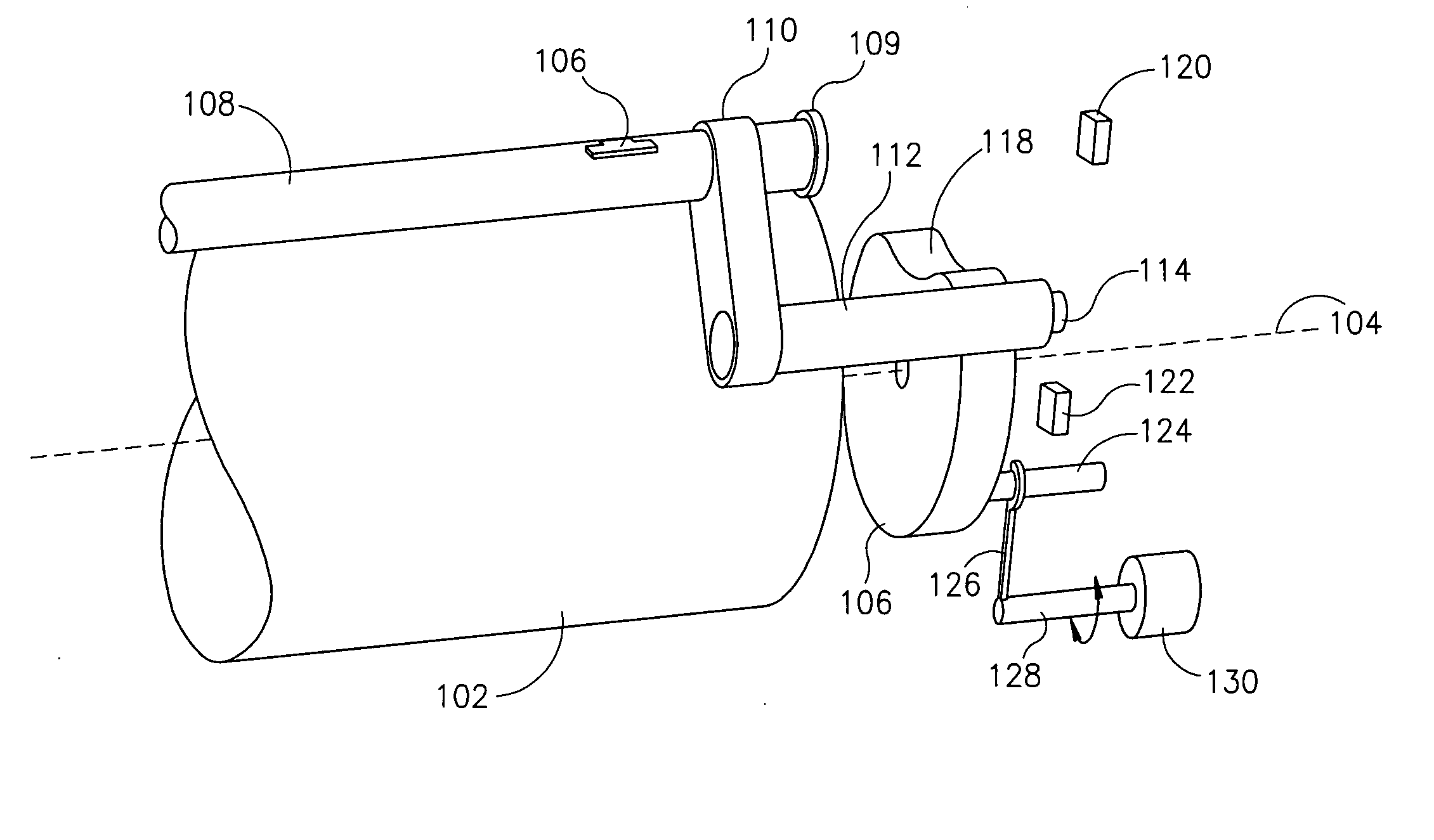
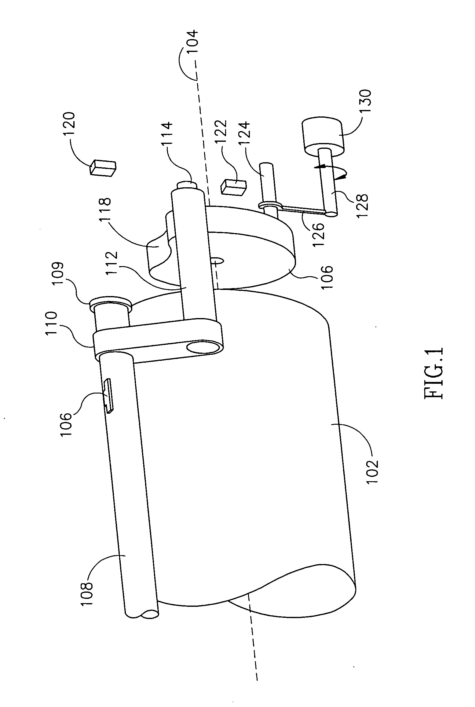
[0056]FIG. 1 shows one end of an impression roller 102 in a printer or copier, in accordance with an embodiment of the invention. The impression roller rotates continuously around an axis 104 during normal operation of the printer or copier. A gripper 106 is opened and closed by the rotation of a gripper control rod 108, which is mounted in a bearing 109 that is attached to the impression roller. Optionally there are one or more additional grippers not shown in the drawing, located for example further to the left of the gripper shown, which are also opened and closed by control rod 108. A lever 110 attaches control rod 108 to a cam follower 112. When cam follower 112 moves radially outward from axis 104, lever 110 causes control rod 108 to rotate in a direction which opens gripper 106. When cam follower 112 moves radially inward, then lever 110 causes control rod 108 to rotate in the other direction, which closes gripper 106. Alternatively, cam follower 112, lever 110, contrail rod ...


PUM


Abstract

A system for printing an image on a printing media, comprising: a) an impression roller; b) a gripper which receives the printing media when said gripper is open, closes to hold the printing media to the impression roller while the image is printed, and opens to release the printing media from the impression roller; and c) at least one sensor which senses whether the gripper is open or closed.

Description

FIELD OF THE INVENTION [0001] The field of the invention is printers and copiers, especially apparatus and methods for monitoring malfunctioning of grippers. BACKGROUND OF THE INVENTION [0002] Printers and copiers often have a photo-sensitive member which receives an image, and an intermediate transfer member, often with a heated blanket, which receives the image from the photo-sensitive member and transfers it to sheet of paper or other printing media on an impression roller. (The printing media will henceforth be referred to as “paper,” but any printing media should be understood.) The intermediate transfer member often has a delicate surface, for example the heated blanket may comprise a release surface with a soft conforming layer underneath, which allows the surface to press against the impression roller with uniform pressure. These characteristics of the intermediate transfer member produce good images on the printing media, but also mean that its surface may be damaged relati...

Claims


Application Information

Patent Timeline
Patent Type & Authority Applications(United States)
IPC IPC(8): B41F9/00
CPCB41J13/223
Inventor BARAZANI, AVIRAPOPORT, SHAUL
Owner HEWLETT PACKARD DEV CO LP
Why Eureka
Try Eureka