Lens-equipped light-emitting diode device and method of manufacturing the same

a technology of light-emitting diodes and lenses, which is applied in the direction of discharge tubes/lamp details, other domestic objects, instruments, etc., can solve the problems of reducing assembly costs, reducing production costs, and reducing assembly costs, so as to improve light extraction efficiency and reliability, and reduce production costs

Inactive Publication Date: 2007-06-28
KK TOSHIBA
View PDF1 Cites 36 Cited by
  • Summary
  • Abstract
  • Description
  • Claims
  • Application Information

AI Technical Summary

Benefits of technology

[0011] In view of the foregoing, an object of the invention is to provide a lens-equipped light-emitting diode which is ...

Problems solved by technology

In the conventional lens-equipped light-emitting diode device, there are the following problems.
There is also generated the problem that mechanical strength or a heat-resistant property is degraded due to poor adhesion between the lens 106 and the outer periphe...

Method used


Image

  • Lens-equipped light-emitting diode device and method of manufacturing the same
  • Lens-equipped light-emitting diode device and method of manufacturing the same
  • Lens-equipped light-emitting diode device and method of manufacturing the same

Examples


first embodiment

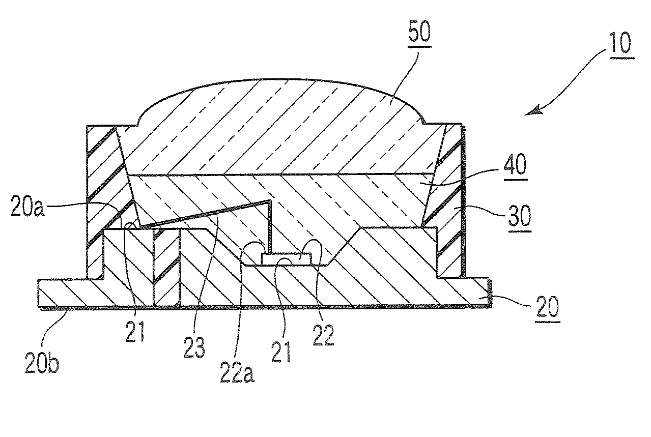
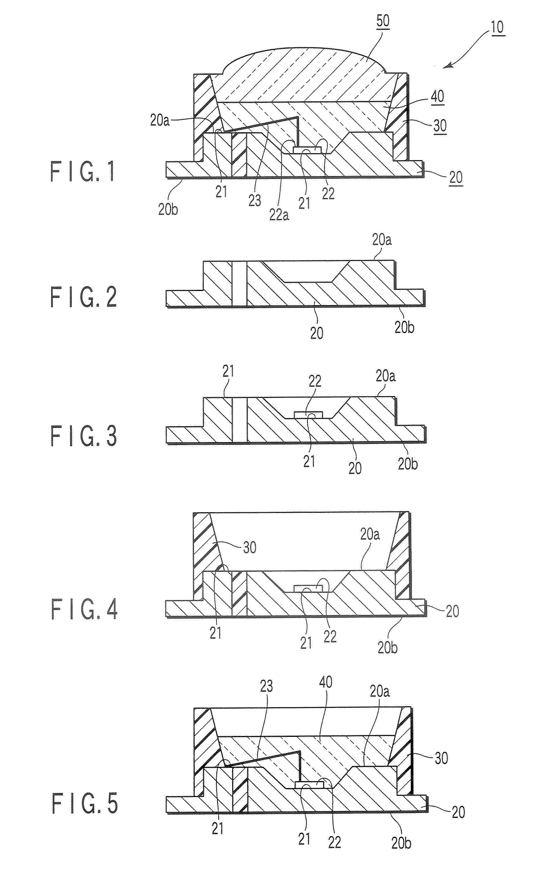
[0030]FIG. 1 is a longitudinal sectional view showing a lens-equipped light-emitting diode device 10 according to the invention. The lens-equipped light-emitting diode device 10 includes a lead frame 20, an outer peripheral unit 30, a sealing portion 40, and a lens unit 50. The lead frame 20 is a support member in which an electrode is formed. The outer peripheral unit 30 is formed on the lead frame 20. The sealing portion 40 is provided in the outer peripheral unit 30 and seals a light-emitting diode 22 and a bonding wire 23. The lens unit 50 is arranged in an upper portion of the sealing portion 40.

[0031] Plural electrodes 21 are formed on the side of a surface 20a of the lead frame 20, and a light-emitting diode 22 is mounted on the electrode 21. A bonding wire 23 is connected to one of the electrodes of the light-emitting diode 22, and the bonding wire 23 is connected to the electrode 21. In FIG. 1, the number 20b designates a backside of the lead frame 20.

[0032] A white color ...

second embodiment

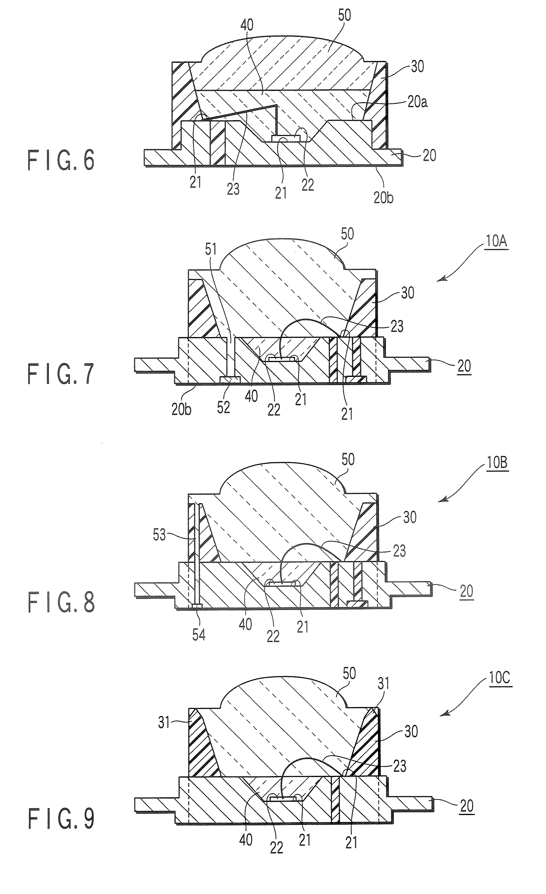
[0039]FIG. 7 is a longitudinal sectional view showing a lens-equipped light-emitting diode device 10A according to the invention. In FIG. 7, the same components as those of FIG. 1 are designated by the same numbers, and detailed description thereof will be omitted.

[0040] A penetration portion 51 is provided in the lens unit 50, and the penetration portion 51 is latched in the lead frame 20 at a front-edge portion 52 of the penetration portion 51. The penetration portion 51 penetrates the lead frame 20 to the backside 20b where the light-emitting diode 22 is not mounted.

[0041] In the lens-equipped light-emitting diode device 10A of the second embodiment, the same effect as the lens-equipped light-emitting diode device 10 can also be obtained. The lens-equipped light-emitting diode device 10A further has the following effect. In the case where the resins forming the outer peripheral unit 30 and the lens unit 50 are different from each other, it is difficult to secure adhesive strengt...

third embodiment

[0042]FIG. 8 is a longitudinal sectional view showing a lens-equipped light-emitting diode device 10B according to the invention. In FIG. 8, the same components as those of FIG. 1 are designated by the same numbers, and detailed description thereof will be omitted.

[0043] A penetration portion 53 is provided in the lens unit 50, and the penetration portion 53 is latched in the lead frame 20 at a front-edge portion 54 of the penetration portion 53. The penetration portion 53 penetrates the outer peripheral unit 30 and the lead frame 20 to the backside 20b where the light-emitting diode 22 is not mounted.

[0044] In the lens-equipped light-emitting diode device 10B of the third embodiment, the same effect as the lens-equipped light-emitting diode device 10A can also be obtained.


PUM

PropertyMeasurementUnit
Transparencyaaaaaaaaaa

Abstract

A lens-equipped light-emitting diode device of the present invention includes a lead frame in which an electrode is formed, a light-emitting diode which is mounted on the electrode of the lead frame, an outer peripheral unit which is made of a first resin, which is provided on the lead frame, and in which a hollow portion is formed while an area including at least the light-emitting diode is exposed in the outer peripheral unit, a sealing portion which is made of a second resin filled in the lead frame of the hollow portion of the outer peripheral unit, and which seals the light-emitting diode, and a lens unit made of a third resin laminated and filled in the sealing portion.

Description

CROSS-REFERENCE TO RELATED APPLICATIONS [0001] This application is based upon and claims the benefit of priority from prior Japanese Patent Application No. 2005-373498, filed Dec. 26, 2005, the entire contents of which are incorporated herein by reference. BACKGROUND OF THE INVENTION [0002] 1. Field of the Invention [0003] The present invention relates to a lens-equipped light-emitting diode device which extracts light from a light-emitting diode through a lens and a method of manufacturing the same, and particularly to a lens-equipped light-emitting diode device which is excellent for light extraction efficiency and reliability and whose production cost can be reduced. [0004] 2. Description of the Related Art [0005]FIG. 13 is a longitudinal sectional view showing a conventional lens-equipped light-emitting diode device 100. In the lens-equipped light-emitting diode device 100, a light-emitting diode element 102 is mounted through a die mounting material (not shown) on a lead frame ...

Claims


Application Information

Patent Timeline
IPC IPC(8): H01J5/02H01J40/14H01L33/50H01L33/54H01L33/56H01L33/60H01L33/62
CPCB29C45/14655B29C45/1671B29L2011/0016H01L33/54H01L33/58H01L2224/48247
Inventor NISHIKAWA, SHOUICHIKOMATSU, TETSUROTAKEZAWA, HATSUOAOKI, YUKINORI
Owner KK TOSHIBA
Why Eureka
Try Eureka