
Motor device utilizing magnetic force to drive a rotor

a motor device and rotor technology, applied in the direction of magnetic circuit rotating parts, magnetic circuit shape/form/construction, piston pumps, etc., can solve the problems of high cost, large space occupation, complicated structure and controlling circuit of brushless motors, etc., to prolong the use life of motors and improve the efficiency of motors

Inactive Publication Date: 2007-06-28
LIU MING HWA +2
View PDF4 Cites 6 Cited by
  • Summary
  • Abstract
  • Description
  • Claims
  • Application Information

AI Technical Summary

Benefits of technology

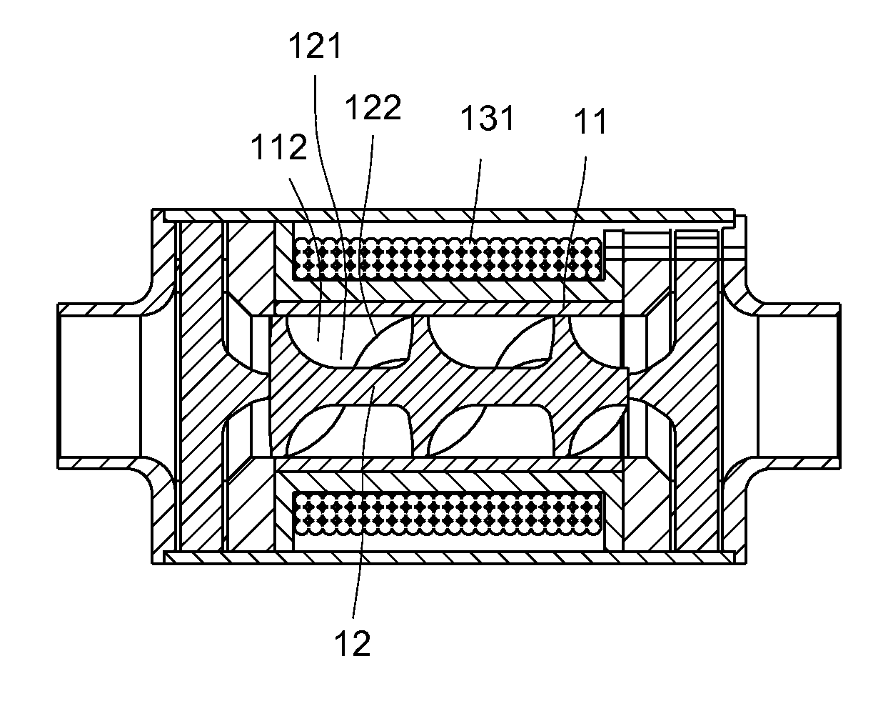
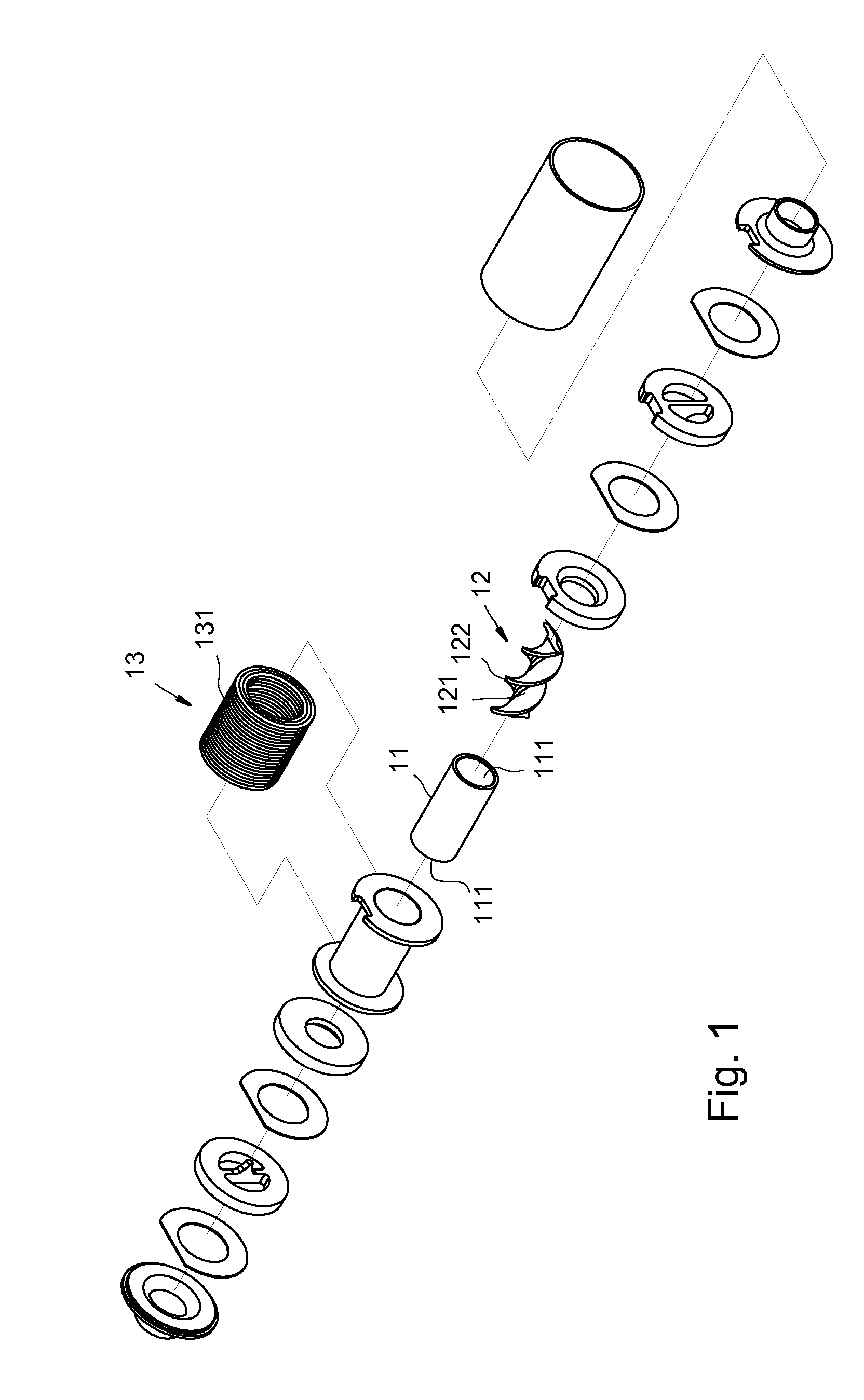
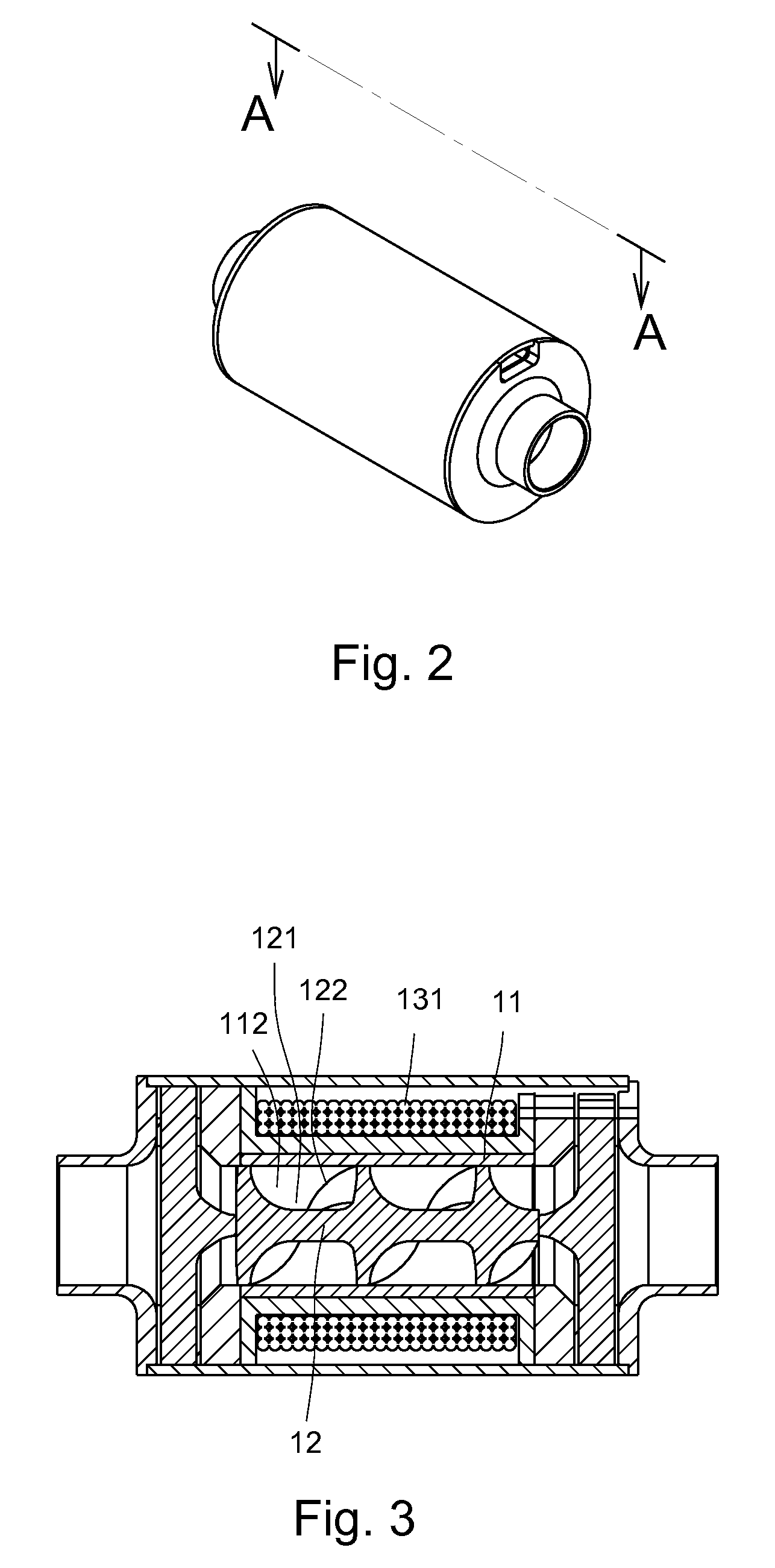
[0006] It is therefore a primary object of the present invention to provide a motor device utilizing magnetic force to drive a rotor. The motor has a brushless structure and equipped with a non-conventional wheel blade type or piston type pump. The using life of the motor is prolonged and the efficiency of the motor is better.
[0008] It is still a further object of the present invention to provide the above motor device which has simple structure and includes fewer components to form a brushless power structure.

Problems solved by technology

Basically, the output power of the brush motor is smaller than the output power of the brushless motor, while the structure and controlling circuit of the brushless motor are more complicated than the structure and controlling circuit of the brush motor.
The above conventional pump device is equipped with the motor so that much room is occupied and the cost is relatively high.
In such case, the cost is still high and it is inconvenient to use the pump device.

Method used


Image

  • Motor device utilizing magnetic force to drive a rotor
  • Motor device utilizing magnetic force to drive a rotor
  • Motor device utilizing magnetic force to drive a rotor

Examples


second embodiment

[0032] Referring to FIGS. 4 to 6 show the present invention, according to FIG. 1 in which the controlling unit 13 further includes at least one stator section 132 containing magnetizable material. The stator section 132 is adjacent to the rotor 12 and positioned between the coil 131 and the rotor 12. Due to the electromagnetic effect of the coil 131, the stator section 132 will create a time-varied magnetic field for more effectively driving the rotor 12.

[0033] The stator 132 can be a block body or a hollow cylindrical body positioned at one end of the rotor 12 between the coil 131 and the rotor 12.

third embodiment

[0034]FIG. 7 shows the present invention, according to FIG. 1 in which the stator 132 is a block body positioned on one side of the rotor 12 between the coil 131 and the rotor 12. This arrangement can also achieve the same effect. Furthermore, the stator section 132 can be formed as an arced piece to more effectively achieve the cut across effect of the magnetic field.

[0035] Certainly, two stator sections 132 can be respectively arranged at one end of the rotor 12 and on one side of the rotor 12 to achieve the same effect. Moreover, the stator section 132 arranged on one side of the rotor 12 can have a permanent magnetic field. The direction of the magnetic lines of the permanent magnetic field is different from the direction of the magnetic lines of the coil 131. Accordingly, the magnetic lines of the permanent magnetic field are guided by the magnetic lines of the stator section 132 at the end of the rotor 12 to compensate / strengthen the magnetic lines of the stator section 132 at...


PUM


Abstract

The present invention relates to a motor device utilizing magnetic force to drive a rotor. The motor device includes a main body, a rotor and a controlling unit. The main body has two openings and an internal chamber. The rotor is magnetic and swingably disposed in the chamber between the two openings. The controlling unit is disposed on outer side of the main body to apply a magnetic force to the rotor for driving the rotor to at least rotate. The rotor is a column body with a certain length. The rotor has a profile corresponding to a configuration of a peripheral wall of the chamber. The outer face of the rotor is formed with at least one spiral groove to define at least one spiral stripe. The rotor is magnetically driven to drive a fluid to flow from one opening to the other opening.

Description

BACKGROUND OF THE INVENTION [0001] The present invention is related to a motor device, and more particularly to a motor device utilizing magnetic force to drive a rotor for driving a fluid. [0002] A conventional pump device serves to drive a fluid to flow within a pipeline. The pump device generally includes a waterwheel or a cylinder communicating with a pipeline. The waterwheel or the cylinder is externally connected with a motor. The motor operates to rotate the waterwheel or reciprocate the cylinder for driving the fluid within the pipeline. Accordingly, the fluid can circularly flow between two positions or transfer from a position to another position. [0003] The motor can be a brushless one or a brush motor. Basically, the output power of the brush motor is smaller than the output power of the brushless motor, while the structure and controlling circuit of the brushless motor are more complicated than the structure and controlling circuit of the brush motor. [0004] The above c...

Claims


Application Information

Patent Timeline
Patent Type & Authority Applications(United States)
IPC IPC(8): H02K5/12H02K17/00H02K1/22F04B17/00
CPCF04D3/02F04D13/0646H02K1/2726H02K7/14H02K57/00H02K99/00H02K17/00
Inventor LIU, MING-HWACHEN, BRIAN D. F.CHIEN, CHIN-PANG
Owner LIU MING HWA
Learn More