Single-Phase Brushless Motor

a single-phase, brushless technology, applied in the direction of motor/generator/converter stopper, dynamo-electric converter control, stopping arrangement, etc., can solve the problems of affecting the operation of the motor, the susceptibility to damage of the switching element or capacitor, and the difficulty of configuring a single-phase motor as a brushless motor, etc., to achieve excellent technology, improve the efficiency of the motor, and reduce power consumption

Inactive Publication Date: 2009-07-16
GK BRIDGE 1
View PDF11 Cites 6 Cited by
  • Summary
  • Abstract
  • Description
  • Claims
  • Application Information

AI Technical Summary

Benefits of technology

[0117]From (1) and (2) above it will be seen that, where instances of rectangular wave driving are compared, power consumption by the single-phase motor of the embodiment was 2.35 [w] versus 3.6 [W] for the conventional 2-phase motor, an improvement of (3.6−2.35) / 3.6=35%.
[0118]From (2) and (3) above it will be seen that changing from rectangular wave driving to sine wave driving of the single-phase motor of the embodiment led to an improvement in power consumption from 2.35 [W] to 2.00 [W], an improvement of (2.35−2.00) / 2.35=15 [%].
[0119]From (1) and (3) above it will be seen that power consumption by the single-phase motor of the embodiment under sine wave driving was 2.00 [W] versus 3.6 [W] for the conventional 2-phase motor, an improvement of (3.6−2.0) / 3.6=44 [%].
[0120]While the 2-phase fan motors to date operate on the basic principle used to drive most fan motors worldwide and are employed in many electronic devices, the single-phase motor of the embodiment affords an improvement of 44 [%] in power consumption. Accordingly, the motor of the embodiment of the present invention represents a technology effective on a global scale, and can be appreciated as an excellent technology for addressing problems of the global environment.
[0121]In addition to the effect of lower power consumption than conventional 2-phase fan motors, the single-phase brushless motor of the present embodiment also has the effects of low vibration, low noise, minimal rotation irregularities, low heat emission, and long life. Specifically, the single-phase brushless motor according to the present embodiment affords low power consumption, as well as reduced vibration and noise caused by eddy current, since eddy current produced in the magnetic members is negligible. Moreover, since the magnetic poles and coils are equal in number, rotation irregularities are minimal. Furthermore, due to the low power consumption and minimal copper loss of the coils, heat emission is low as well. The lower heat emission and reduced vibration have the effect of extending the life of the motor as well.
[0122]FIGS. 21A, 21B through 27A, 27B are sectional views depicting other exemplary configurations of the motor unit. In the drawings, parts corresponding to parts of the motor unit 100 of FIGS. 1A and 1B have been assigned identical symbols.

Problems solved by technology

However, when a single-phase employing an inverter drive is started up, there is considerable current flow to the secondary winding and the capacitor during startup, creating the problem of susceptibility to damage of the switching elements or capacitor.
Accordingly, a problem encountered in the prior art is the difficulty of configuring a single-phase motor as a brushless motor.

Method used


Image

  • Single-Phase Brushless Motor
  • Single-Phase Brushless Motor
  • Single-Phase Brushless Motor

Examples


embodiment 2

D. Embodiment 2

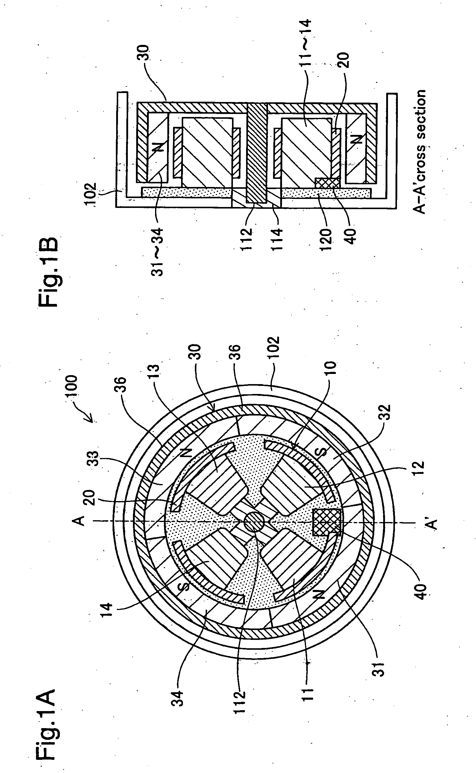
[0130]FIGS. 28A and 28B are side views depicting the configuration of the motor unit of a single-phase brushless motor pertaining to Embodiment 2 of the present invention. This motor unit 100g has a stator portion 10 and a rotor portion 30 each of generally round tubular shape. The stator portion 10 has four coils 11-14 arranged in a generally cross-shaped pattern, and a magnetic sensor 40 positioned at a center location between two of the coils 11, 12. The magnetic sensor 40 is used to detect the position of the rotor portion 30 (i.e. the phase of the motor). Magnetic yokes 20 formed of magnetic material are positioned at the inside peripheral side of the coils 11-14, at locations midway between neighboring coils. The magnetic yokes 20 are used to position the rotor portion 30 when the motor is stopped. In preferred practice positioning magnetic yokes 20 will have material, thickness, pattern of placement, etc. selected so that positioning is possible under condition...

modification examples

E. Modification Examples

[0142]The present invention is not limited to the embodiments described hereinabove, and may be reduced to practice in various other ways without departing from the spirit thereof. Modifications such as the following would be possible, for example.

modification example 1

E1. Modification Example 1

[0143]In the preceding embodiments, the magnetic members or magnetic yokes 20 are provided for each individual coil, but the coil array may instead be furnished with magnetic members differing in number from the number of coils. In this case, the magnetic members will preferably be arranged in such a way that, with the single-phase brushless motor at a stop, the magnetic members will be attracted by the magnet array and thereby bring the motor to a halt at a position with the centers of the permanent magnets offsetted from the centers of the magnetic coils. However, an advantage of providing a magnetic member for each coil is the ease of achieving weight balance of the magnet array as a whole.


PUM


Abstract

The single-phase brushless motor according to one aspect of the present invention includes a coil array having a plurality of magnetic coils 11-14; a magnet array having a plurality of permanent magnets 31-34; a magnetic sensor 40 for detecting relative position of the magnet array and the coil array; and a drive control circuit that, utilizing the output signal SSA of the magnetic sensor, generates application voltage for driving the coil array with a single-phase drive signal. The coil array includes a magnetic member 20. This magnetic member 20 is constituted such that, with the single-phase brushless motor at a stop, the centers of the permanent magnets 31-34 come to a stop at locations offsetted from the centers of the magnetic coils 11-14, due to attraction of the magnetic member 20 by the magnet array.

Description

TECHNICAL FIELD[0001]The present invention relates to a single-phase brushless motor that utilizes permanent magnets and magnetic coils.BACKGROUND ART[0002]In the motor industry, both 1-phase motors and 2-phase motors are referred to collectively as “single-phase motors.” However, the term single-phase motor will be used herein to mean phase 1 motors only, and excludes phase 2 motors.[0003]Brushless motors that utilize permanent magnets and magnetic coils are known from publications such as JP 2001-298982A, for example.[0004]In this prior art electric motor, control is carried out using an on / off signal from a digital magnetic sensor. Specifically, the timing for reversing the polarity of the voltage applied to the magnetic coils is determined using an on / off signal from the digital magnetic sensor. A three-phase drive signal is often used as the drive signal.[0005]Conventional brushless motors utilized a drive signal with two or more phases; none use a single-phase drive signal. Th...

Claims


Application Information

Patent Timeline
Patent Type & Authority Applications(United States)
IPC IPC(8): H02K29/03H02K29/08H02P21/05H02P21/34H02P21/36H02P23/00H02P23/04H02P23/28H02P27/08
CPCH02K29/03H02K29/08H02P6/24H02P6/182H02P6/22H02P6/008H02P6/26G04C3/14
Inventor TAKEUCHI, KESATOSHISUGIMOTO, MAMORU
Owner GK BRIDGE 1
Why Eureka
Try Eureka