Liquid ejection head, method of manufacturing liquid ejection head, and image forming apparatus

Inactive Publication Date: 2007-06-28
FUJIFILM CORP
View PDF4 Cites 15 Cited by
  • Summary
  • Abstract
  • Description
  • Claims
  • Application Information

AI Technical Summary

Benefits of technology

[0027] According to an image forming apparatus of this kind, the liquid ejection head can be miniaturized without giving rise to structural problems, and accordingly the overall image forming apparatus can be downsized.
[0028] As described above, according to the present invention, beneficial effects are obtained in that high-density wires can be manufactured readily in a three-dimensional configuration while the structural rigidity and airtightness is ensured in the composition of the liquid ejection head.
[0029] In other words, since there are no connecting sections at intermediate points of the wires, then reliable electrical connections can be ach

Problems solved by technology

However, in the invention described in Japanese Patent Application Publication No. 9-314831, there is a problem in that since electrical contacts are provided, the reliability of the connections in the contact sections is poor.
Furthermore, it is hard to actualize the invention since it is difficult to achieve accurate positioning in the cases of high-density wires.
Since the cover member is formed by inflecting a film material, it does not maintain structural strength and does not function as a structural member.
Moreover, in the invention described in Japanese Patent Application Publication No. 9-314833, in compositional terms, it is necessary to connect the electrical wires by placing two substrates in contact with each other, and therefore it is difficult to achieve accurate positioning in cases of high-density wires, thus leading to a loss of reliability in the connections.
Furthermore, in the invention described in Japanese Patent Applicatio

Method used


Image

  • Liquid ejection head, method of manufacturing liquid ejection head, and image forming apparatus
  • Liquid ejection head, method of manufacturing liquid ejection head, and image forming apparatus
  • Liquid ejection head, method of manufacturing liquid ejection head, and image forming apparatus

Examples


second embodiment

[0133] Next, the liquid ejection head according to the present invention is described.

[0134] In the second embodiment, electrical wires are formed on the inner side of the partition walls forming the common liquid chamber 55.

first embodiment

[0135]FIG. 12 shows a die required in order to form electrical wires on the inner side of walls 134. The die includes an outer die 131 and an inner die 130, and projecting sections 132 for creating grooves for forming electrodes are provided with the inner die 130. Very fine metal particles of copper, or the like, adhere to the surfaces of the projecting sections by means of a step similar to that in the process of the

[0136] Epoxy resin is caused to flow into a space between the inner die 130 and the outer die 131, and a print head is formed by a method similar to that described in the first embodiment. Since the electrodes are formed on the inner side, a structure for preventing corrosion and shorting is obtained by covering all of the electrodes with an inorganic insulating film, such as silica, alumina or the like, or an organic insulating film. In FIG. 12, the die have a cube shape, but by forming the die with a frustum shape of square pyramid (i.e., a structure where the upper ...

third embodiment

[0151] A third embodiment according to the present invention is a further method of manufacturing a liquid ejection head according to an embodiment of the present invention. This method of manufacture is described below with reference to FIGS. 17A to 17G

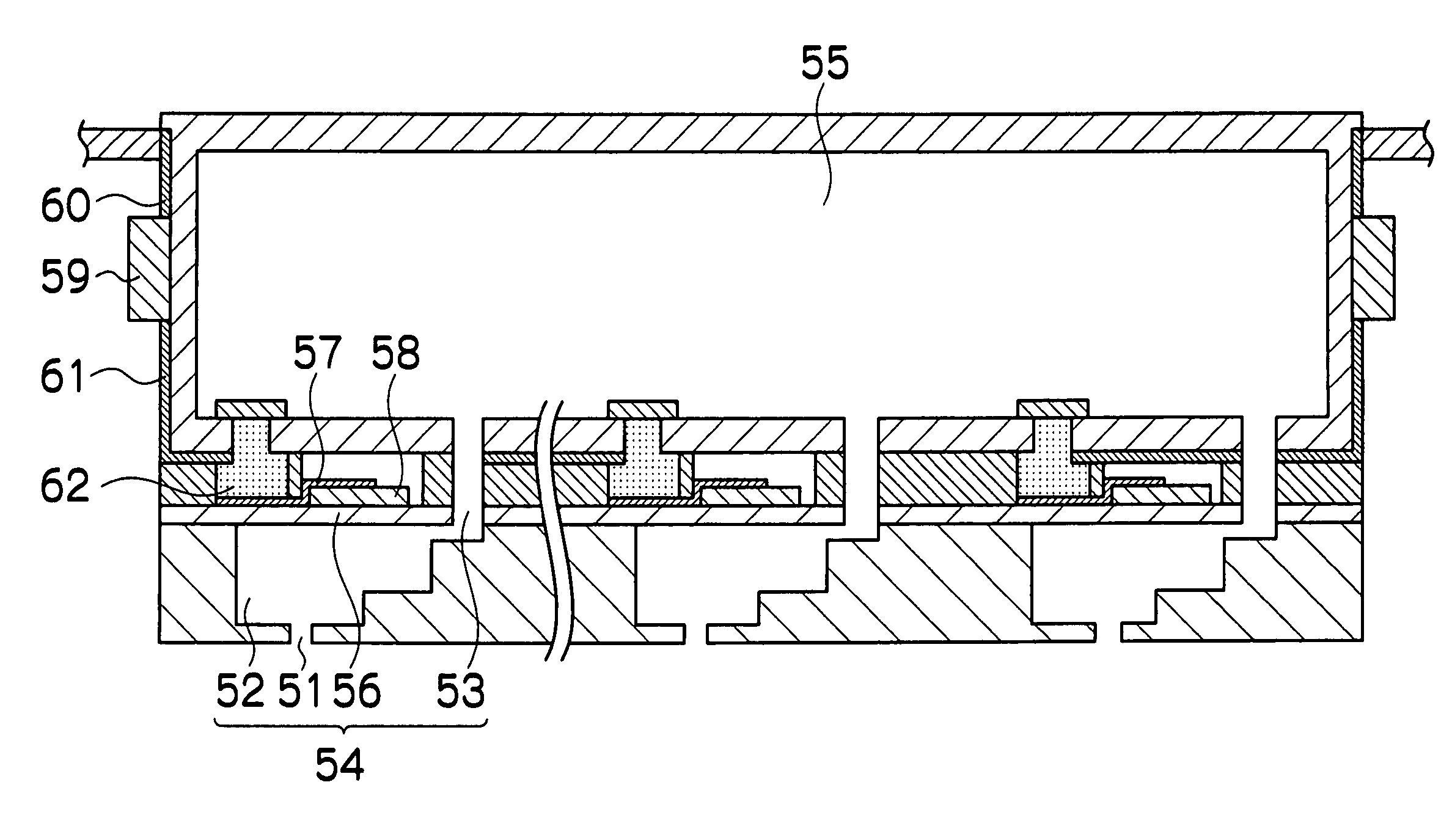
[0152] As shown in FIG. 17A, piezoelectric elements are formed on top of the diaphragm 56 which is included in the pressure chamber units 54 shown in FIG. 4. The diaphragm 56 also serves as a common electrode and it has holes each of which constitutes a portion of an ink supply port 53. Although not shown in FIG. 17A, the surface of the diaphragm 56, which also serves as the common electrode, is covered with a thin insulating film in the regions other than the portions where piezoelectric elements 58 are formed. Thereupon, as shown in FIG. 17B, individual electrodes 57 are formed respectively on top of the piezoelectric elements 58.

[0153] A photosensitive resin film 120a is then applied on the top by spin coating, or another techniq...


PUM


Abstract

The liquid ejection head includes: a piezoelectric body which generates pressure for ejecting liquid; a pressure chamber which is connected to a nozzle; a common liquid chamber which is arranged across the piezoelectric body from the pressure chamber and has at least five molded walls that are integrally molded from a resin material; groove-shaped wires which include a first wire and a second wire and are formed on at least two of the molded walls of the common liquid chamber; a liquid supply flow channel which is provided in one of the molded walls that is adjacent to the pressure chamber in such a manner that the liquid supply flow channel is connected with the pressure chamber; and an electronic circuit which is arranged on one of the molded walls of the common liquid chamber, wherein the first wire is connected to the piezoelectric body and the second wire is connected to the electronic circuit.

Description

BACKGROUND OF THE INVENTION [0001] 1. Field of the Invention [0002] The present invention relates to a liquid ejection head, a method of manufacturing a liquid ejection head, and an image forming apparatus, and more particularly, it relates to an electronic circuit for controlling liquid ejection, an electrical wiring arrangement and structure, and a method of manufacturing such a structure. [0003] 2. Description of the Related Art [0004] As an image forming apparatus in the related art, an inkjet printer (inkjet recording apparatus) is known, which comprises an inkjet printer head (liquid ejection head) having an arrangement of a plurality of liquid ejection nozzles and which records images on a recording medium by ejecting ink (liquid) from the nozzles toward the recording medium while causing the inkjet head and the recording medium to move relatively to each other. [0005] Such an inkjet head of an inkjet printer of this kind has pressure generating units, each comprising, for ex...

Claims


Application Information

Patent Timeline
IPC IPC(8): B41J2/045
CPCB41J2/1603B41J2/1637
Inventor KOJIMA, TOSHIYAENOMOTO, KATSUMI
Owner FUJIFILM CORP
Why Eureka
Try Eureka