Image sensing apparatus and correction method

Inactive Publication Date: 2007-06-28
CANON KK
View PDF6 Cites 23 Cited by
  • Summary
  • Abstract
  • Description
  • Claims
  • Application Information

AI Technical Summary

Benefits of technology

[0015] The present invention has been made in consideration of the above situation, and has as its object to reduce the effects on an image caused

Problems solved by technology

With these solid state image sensing devices, it is known that defective pixels occurring in the manufacturing process are one cause of a decreased image quality and decreased manufacturing yield.
Firstly, defective pixels are assessed, for example, when the solid state image sensing device is shipped from the factory, using output values obtained by exposing the solid state image sensing device for a standard charge accumulation period under prescribed conditions.
On the other hand, dark current is known to occur with solid state image sensing devices due to factors such as temperature.
However, because this is merely subtraction involving sensed images and black images, noise due to the random component of both images is added, which may conversely prevent improvements in image quality.
However, in the case where this threshold value is set based on the result of subtracting dark images from sensed images, noise cannot be accurately judged if luminance

Method used


Image

  • Image sensing apparatus and correction method
  • Image sensing apparatus and correction method
  • Image sensing apparatus and correction method

Examples


Embodiment Construction

[0036] Preferred embodiments of the present invention will be described in detail in accordance with the accompanying drawings.

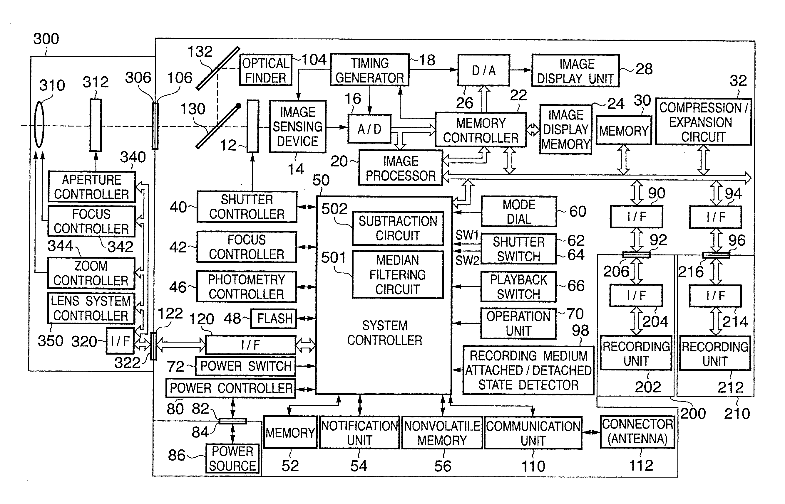
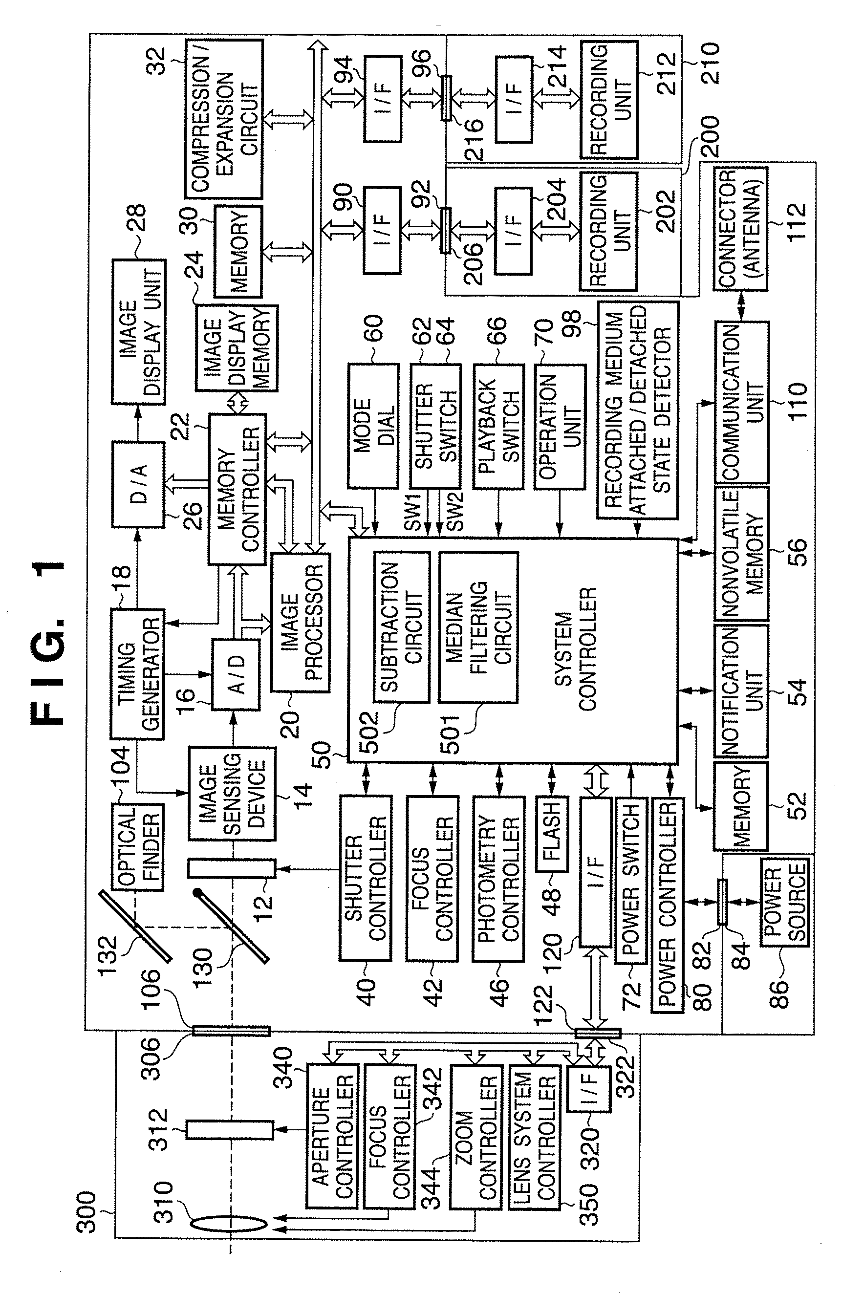
[0037]FIG. 1 is a block diagram showing the configuration of an image sensing apparatus having an image processing function in an embodiment of the present invention. The present embodiment is described taking a digital camera as an example of an image sensing apparatus. Note that the image sensing apparatus may be a digital video camera, a mobile terminal with camera (including a mobile telephone with camera), a scanner or the like, and that application of the present invention is possible provided the apparatus is capable of converting a subject optical image and outputting an electrical image signal.

[0038] As shown in FIG. 1, the image sensing apparatus of the present embodiment is configured primarily by a camera body 100 and an interchangeable lens unit 300.

[0039] In the lens unit 300, 310 is an image sensing lens composed of a plurality of lens, 312...


PUM


Abstract

An image sensing apparatus includes an image sensing device having a plurality of pixels, a smoothing unit that smoothes a first dark image signal acquired with the image sensing device shielded from light; a subtraction unit that subtracts a second dark image signal from the first dark image signal; an extraction unit that extracts, as a defective pixel of the image sensing device, a pixel of which an obtained difference is outside a preset range; and a correction unit that corrects, out of subject image signals output from the image sensing device, an image signal of the defective pixel extracted by the extracting unit, using an image signal of a pixel peripheral to the defective pixel.

Description

BACKGROUND OF THE INVENTION [0001] 1. Field of the Invention [0002] The present invention relates to an image sensing apparatus and a correction method, and more specifically to a technique for correcting the output of an image sensing device used in an image sensing apparatus. [0003] 2. Description of the Related Art [0004] Conventionally, solid state image sensing devices such as CCD and CMOS sensors are generally used in digital cameras, video cameras, and other image sensing apparatuses. With these solid state image sensing devices, it is known that defective pixels occurring in the manufacturing process are one cause of a decreased image quality and decreased manufacturing yield. Given the difficulty in completely eliminating defective pixels, it is generally known that improvement in image quality can be achieved by interpolation using pixels around the defective pixel. [0005] A known method for correcting signals output from defective pixels is disclosed in the Background Art...

Claims


Application Information

Patent Timeline
IPC IPC(8): H04N9/64H04N5/335H04N5/361H04N5/367H04N5/369H04N5/374H04N5/376H04N5/378H04N101/00
CPCH04N5/361H04N5/367H04N25/68H04N25/63
Inventor OSHIMA, KOJI
Owner CANON KK
Why Eureka
Try Eureka