Display device

a display device and structure technology, applied in the field of display device structure, can solve the problems of high polarization degree of polarizing plate, difficult to perform display with a higher contrast ratio by the method, and inability to suppress light leakage, etc., to achieve simple and easy structure and improve the contrast ratio of the display device.

Inactive Publication Date: 2007-06-28
SEMICON ENERGY LAB CO LTD
View PDF99 Cites 27 Cited by
  • Summary
  • Abstract
  • Description
  • Claims
  • Application Information

AI Technical Summary

Benefits of technology

[0008] A method for improving a contrast ratio by using three polarizing plates as described in Patent Document 1 can be realized by using an inexpensive polarizing plate; however, it is difficult to perform display with a higher contrast ratio by the method. Although stacking an additional polarizing plate improves a contrast ratio, it cannot suppress slight light leakage. This is because wavelength dependency of an absorption property is not constant, that is, an absorption property in a specific wave length region is lower than that in another wave length region. In other words, light is hardly absorbed only in the specific region. The same kind of polarizing plates are generally used; therefore, even if polarizing plates are stacked to improve contrast, a wavelength region in which light is not easily absorbed remains as it is. This causes the aforementioned slight light leakage. The light leakage prevents a contrast ratio from being enhanced.
[0009] In view of the aforementioned problems, an object of the invention is to provide a display device having a high contrast ratio by a simple and easy method. Another object of the invention is to manufacture a high-performance display device at low cost.
[0015] A simple and easy structure in which a plurality of different polarizing plates are provided can improve a contrast ratio of a display device.

Problems solved by technology

Further, it is a problem that a polarizing plate having a high polarization degree is expensive.
A method for improving a contrast ratio by using three polarizing plates as described in Patent Document 1 can be realized by using an inexpensive polarizing plate; however, it is difficult to perform display with a higher contrast ratio by the method.
Although stacking an additional polarizing plate improves a contrast ratio, it cannot suppress slight light leakage.
This causes the aforementioned slight light leakage.

Method used


Image

  • Display device
  • Display device
  • Display device

Examples


embodiment mode 2

[0043] In this embodiment mode, description is made of a display device including a retardation film in addition to stacked polarizing plates, which is different from

embodiment mode 1

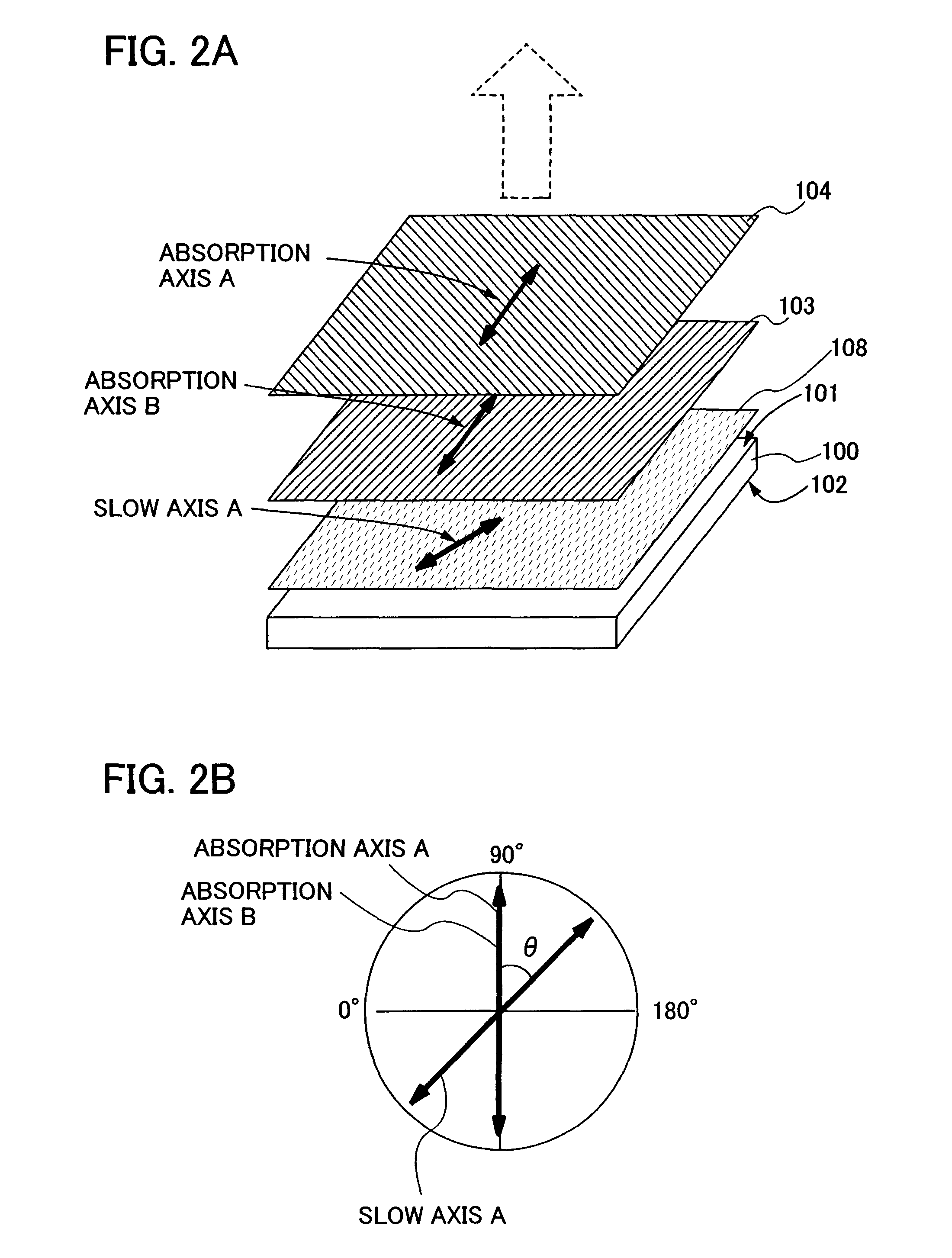
[0044]FIGS. 2A and 2B show a display device including a retardation film in addition to stacked polarizing plates each having an extinction coefficient of an absorption axis which is different from that of an absorption axis of another polarizing plate. A retardation film and stacked polarizing plates each having an extinction coefficient of an absorption axis which is different from that of an absorption axis of another polarizing plate are provided in this order outside the light-transmissive substrates, that is, on sides which are not in contact with the layer having a display element. A first retardation film 108, first polarizing plate 103 and a second polarizing plate 104 are provided on the first substrate 101 side. Here, an extinction coefficient of absorption axis B of the first polarizing plate 103 and that of absorption axis A of the second polarizing plate 104 are different. A combination of a retardation film which is a λ / 4 plate in this case and stacked polarizing plat...

embodiment mode 3

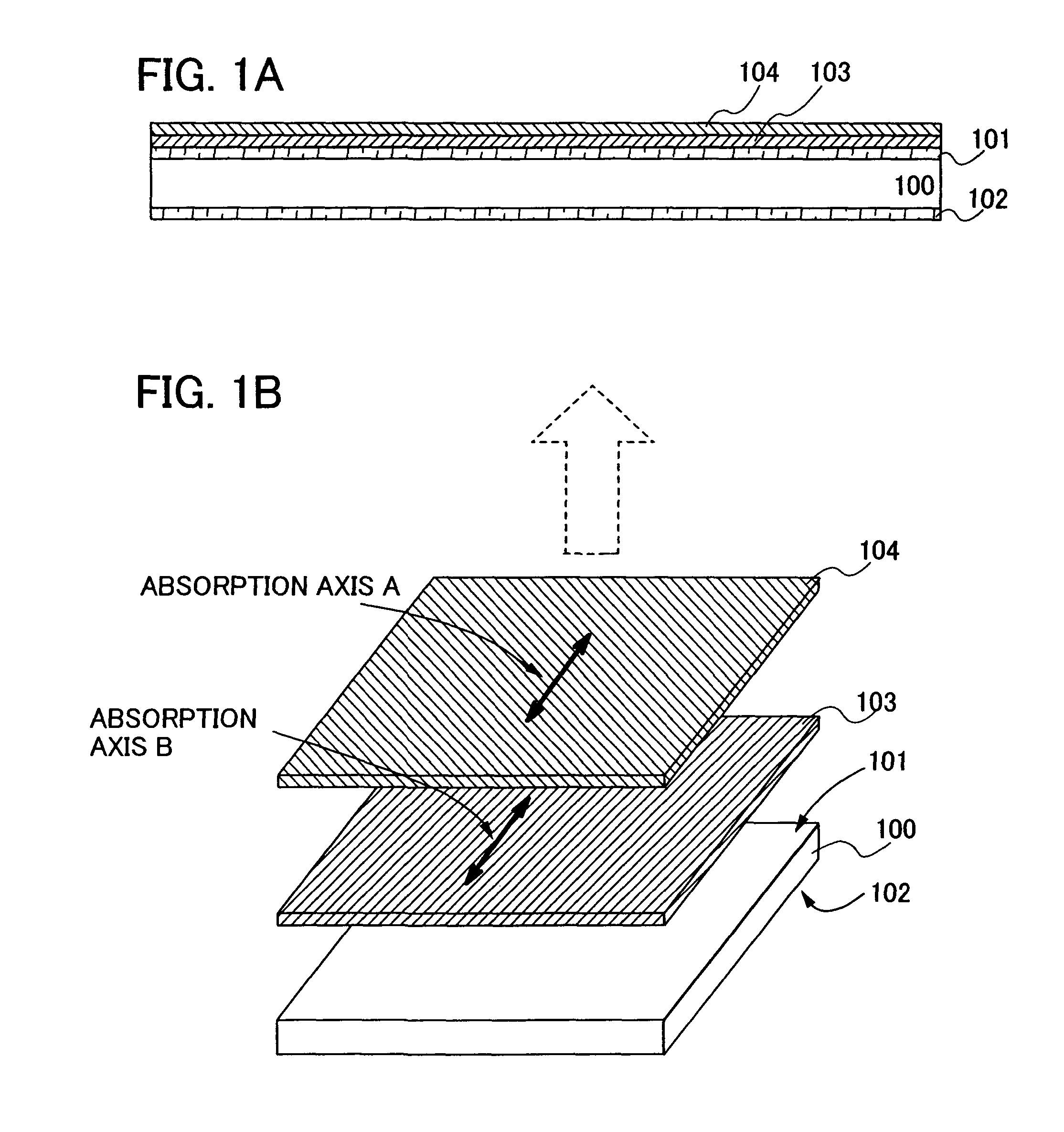
[0051] In this embodiment mode, description is made of a display device including a pair of stacks of polarizing plates in which each polarizing plate has an extinction coefficient of an absorption axis which is different from that of an absorption axis of another polarizing plate, which is different from embodiment modes described above, with reference to FIGS. 3A and 3B. FIG. 3A shows a cross sectional view of a display device provided with a pair of polarizing plates having a stacked structure, and FIG. 3B shows a perspective view of the display device.

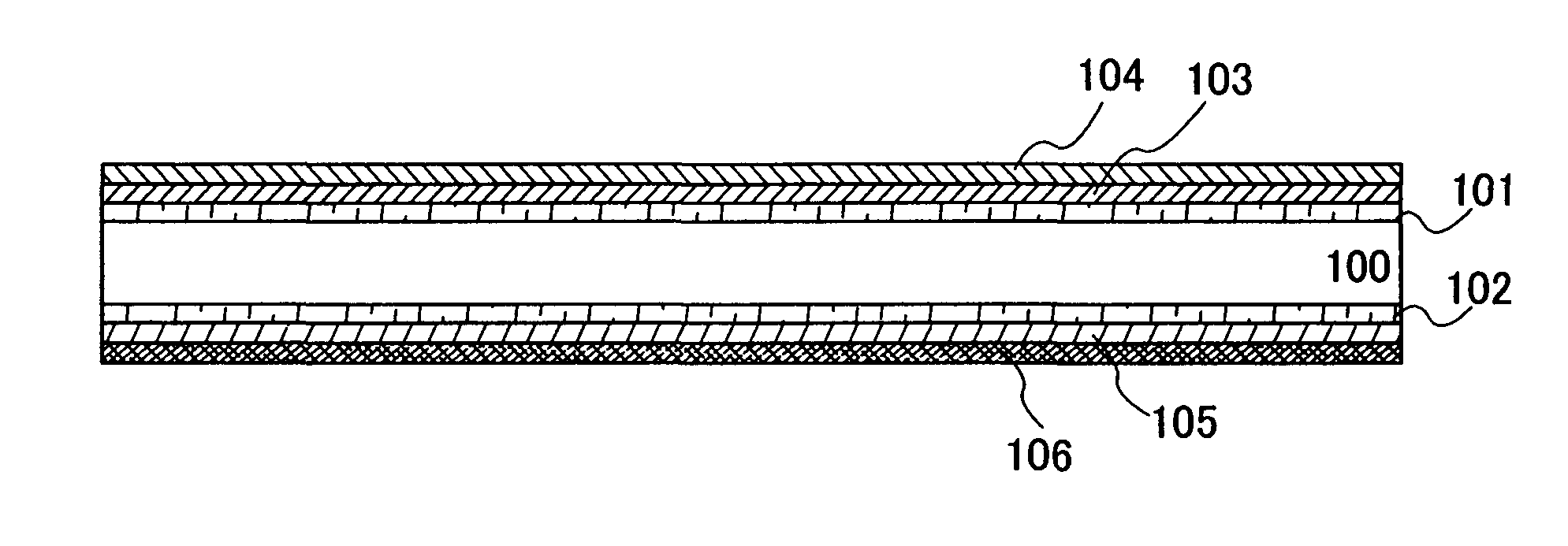
[0052] As shown in FIG. 3A, a layer 100 having a display element is sandwiched between the first substrate 101 and the second substrate 102 which are arranged so as to face each other. Each of the substrates are a light-transmissive substrate. The substrates can be formed of, for example, a glass substrate such as barium borosilicate glass or aluminoborosilicate glass, a quartz substrate, or the like. Further, a substrate formed o...


PUM

PropertyMeasurementUnit
sizeaaaaaaaaaa
thicknessaaaaaaaaaa
extinction coefficientaaaaaaaaaa

Abstract

An object of the invention is to provide a display device having a high contrast ratio by a simple and easy method. Another object of the invention is to manufacture such a high-performance display device at low cost. In a display device having a display element between a pair of light-transmissive substrates, polarizing plates each having an extinction coefficient of an absorption axis which is different from that of an absorption axis of another polarizing plate are stacked to be provided. At that time, the stacked polarizing plates are arranged so as to be in a parallel nicol state. A wave plate and a retardation film may be provided between the stacked polarizing plates and the substrates.

Description

BACKGROUND OF THE INVENTION [0001]1. Field of the Invention [0002] The present invention relates to a structure of a display device. 2. Description of the Related Art [0003] A so-called flat panel display, which is a display device that is very thin and lightweight as compared to the conventional cathode-ray tube display device, has been developed. A liquid crystal display device having a liquid crystal element as a display element, a light emitting device having a self-light emitting element, an FED (field emission display) using an electron beam, and the like compete in the market of flat panel displays. Therefore, lower power consumption and a higher contrast ratio are demanded in order to increase the added value and to differentiate from other products. [0004] In general, a liquid crystal display device is provided with one polarizing plate over each of substrates to keep a contrast ratio. The higher the contrast ratio is, the more clearly black display is performed. Therefore,...

Claims


Application Information

Patent Timeline
Patent Type & Authority Applications(United States)
IPC IPC(8): G02F1/1335
CPCG02B5/3025G02B27/28G02F1/133528G02F2001/133531G02F2001/133638G02F1/133531G02F1/133638G02F1/1335
Inventor ISHITANI, TETSUJIEGI, YUJINISHI, TAKESHI
Owner SEMICON ENERGY LAB CO LTD
Why Eureka
Try Eureka