Micro-manipulator

a micro-manipulator and hand-held technology, applied in the field of micro-manipulators, can solve the problems of unknowing operator how much force to apply to the gripper, the resistance of the micro-material, and the hardness or softness of the object,

Inactive Publication Date: 2007-06-28
NISCA KK
View PDF5 Cites 5 Cited by
  • Summary
  • Abstract
  • Description
  • Claims
  • Application Information

AI Technical Summary

Benefits of technology

[0009] In accordance with a further aspect of the present invention, gripping determination device/means determine that the grippers have gripped a micro-material when a differential value of the difference in time of the target drive amount and the drive amount detected by the drive amount detection device/means is smaller than a preset value. The resilience value calculating device/means can calculate a resilience value using an equation of k=F/Δθ, where F is the actuator drive force, Δθ is a difference between the actuator target drive

Problems solved by technology

However, the operation of conventional micro-manipulators is such that the resilience of the micro-material, in other words, the hardness or softness of the object, is unknown to the operator as the micro-material is gripped while an operator viewed it on a screen.
For that reason, the operator does not know exactl

Method used


Image

  • Micro-manipulator
  • Micro-manipulator
  • Micro-manipulator

Examples


Embodiment Construction

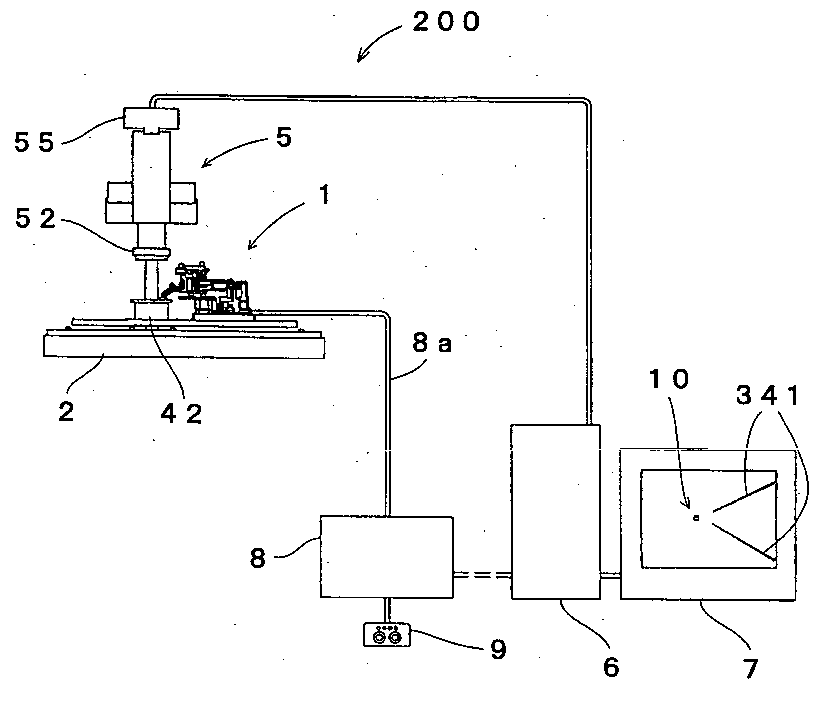
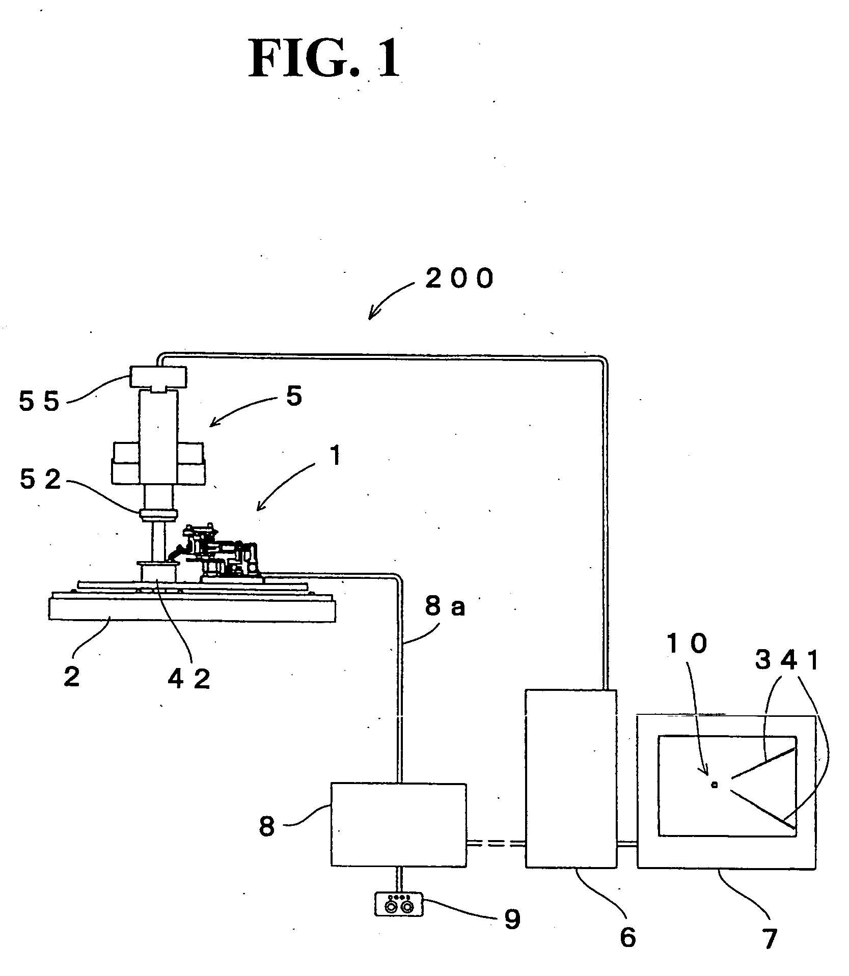
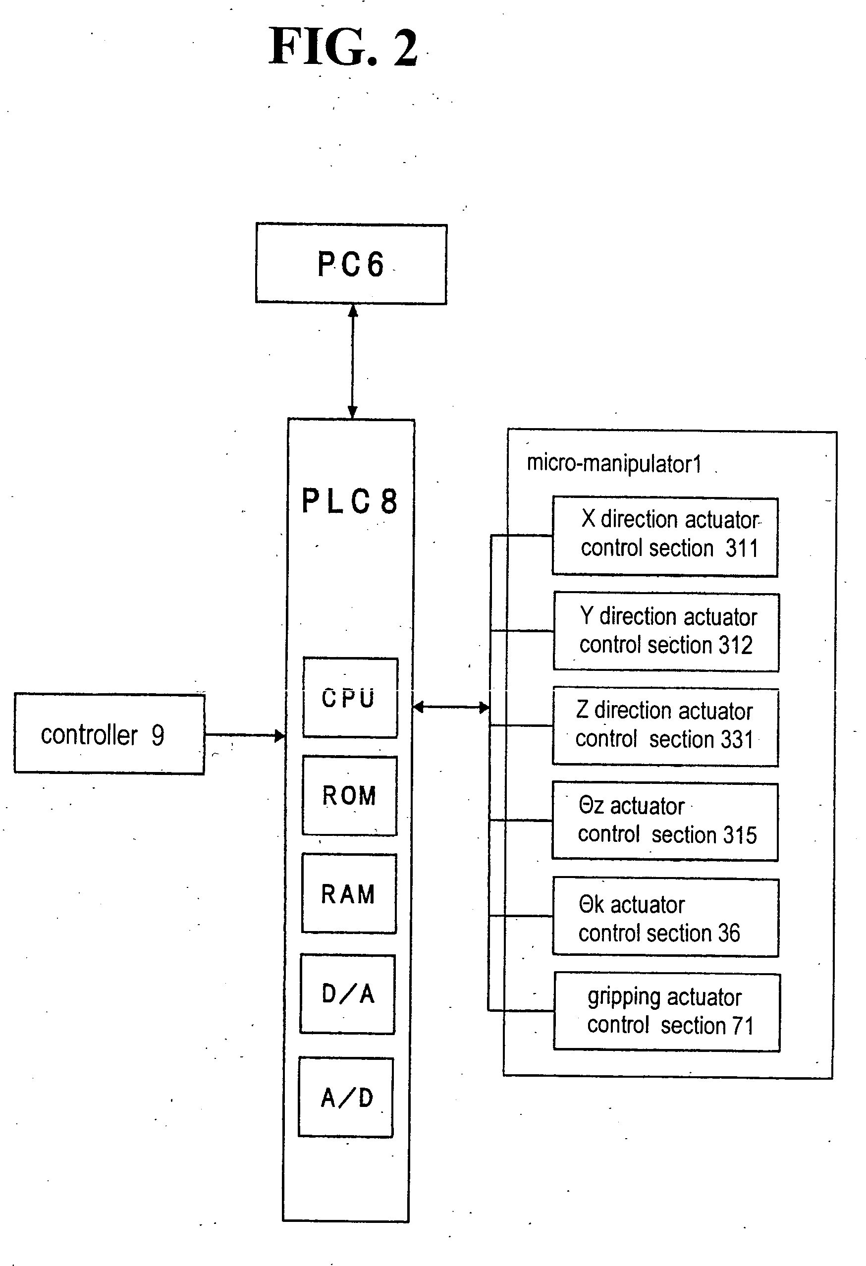
[0018] As shown in FIG. 1, a micro-material handling system 200 of this embodiment of the present invention is provided a micro-manipulator 1 fastened to a surface plate 2 for handling cells; a microscope 5 for viewing cells placed on an XY stage (moving stage) 42; a personal computer (hereinafter referred to as a PC) 6; and a programmable logic controller (hereinafter referred to as a PLC) 8 as a part of electrical power control device / means for controlling the micro-manipulator 1 as a slave computer of the PC6, grip judging device / means, resilience value computing device / means, part of the resilience value output device / means, part of the drive amount detection device / means, the current setting device / means, and the maximum current setting device / means.

[0019] An I / O cable for I / O with the PLC8, an output cable to a monitor 7 such as an LCD device, and an input cable from the CCD camera 55 mounted on the microscope 5 are each connected to the PC 6. One end of a connecting cable 8a...


PUM


Abstract

A micro-manipulator has grippers for gripping micro-material; an actuator for driving the grippers; a drive amount detection device for detecting a drive amount of the actuator; a power control device for controlling power supplied to the actuator so that a difference in a target drive amount of the input actuator and a drive amount detected by the drive amount detection device is small, after at least the grippers touch the micro-material; a gripping determination device for determining that grippers have gripped the micro-material based on the difference; and a resilience value calculation device for calculating a resilience value that represents a degree of softness of the micro-material by dividing the actuator drive force that is equivalent to the repulsive force of micro-material gripped by the grippers in proportion to power supplied to the actuator via the power control device.

Description

BACKGROUND OF THE INVENTION AND RELATED ART STATEMENT [0001] The present invention relates to micro-manipulators, and particularly to micro-manipulators that use gripping fingers to grip resilient micro-material. [0002] Conventionally, micro-manipulators are used to assemble micro-parts or to handle cells. Generally, a micro-manipulator has a gripping mechanism for moving the leading ends of gripping fingers to grip micro-objects. (See patent publication 1, for example) Also, because the material to be gripped is minute, an operator observes at the object through a microscope with the naked eye, or observes images of the object output to a monitor such as a display via a camera mounted on the microscope, in order to operate the micro-manipulator. (See patent publication 2, for example) [0003] If the micro-material to be gripped is derived from a living body, such as a cell, the micro-manipulator needs to be operated while visually checking the degree of deformation of the cell, in o...

Claims


Application Information

Patent Timeline
IPC IPC(8): B66C3/00
CPCB25J7/00
Inventor MOCHIZUKI, NAOTOKANEKO, HIROFUMIKOUNO, MASAHIRO
Owner NISCA KK
Why Eureka
Try Eureka