System of energy-efficient and constant-pressure parallel-coupled fluid-transport machines

a fluid-transport machine and energy-efficient technology, applied in the direction of positive displacement liquid engine, process and machine control, instruments, etc., can solve the problems of complex operation inability to meet the requirements of single-machine fluid-transport systems, and increasing the complexity of parallel-coupled fluid-transport machines

Inactive Publication Date: 2007-06-28
HUANG WEN CHENG
View PDF5 Cites 28 Cited by
  • Summary
  • Abstract
  • Description
  • Claims
  • Application Information

AI Technical Summary

Benefits of technology

[0022] According to the principles mentioned above, and based on the data shown in FIG. 6 and FIG. 7, the performance curve of FIG. 8 can be mathematically expressed as:
[0023] Adopt the performance curve mathematically expressed by equation (41); the recalculated total flow rate will be 40 cfs, and the flow rates of all outlets are almost identical, and the pressures thereof are also uniform, as shown in the portion for three parallel-coupled machines of FIG. 10. According to the same method, the rotation speed required by two parallel-coupled machines can also be worked out, and the rotation speed thereof should be raised to 1850 rpm. As shown in the portion for two parallel-coupled machines of FIG. 10, the flow rates of all outlets are also almost identical, and the errors of the pressures are within only 2%.
[0024] As to the equal-efficiency curves in FIG. 1, they cannot be deduced theoretically but are obtained experimentally form practical operation by the manufacturer, and those data is no more further analyzed but will be used directly.

Problems solved by technology

To mass-produce those precise, delicate and miniature products in low cost, the current high-tech factories grow in scale continuously, and the quality requirements thereof also become more and more strict, which is a challenge for the building companies of the high-tech factory and the facility engineers who maintain the high-tech factory, and which also drives the related personnel to zealously research solutions or develop new technologies to fulfill the requirements.
However, in the current high-tech factories, the scale of the factory is enlarged continuously, and the fabrication procedures also become more and more flexible, in order to reduce the fabrication cost and to achieve the product diversification, and therefore, a single-machine fluid-transport system can no more meet the requirement.
The operation of parallel-coupled fluid-transport machines is more complicated and crucial than that of a single fluid-transport machine, and just an imprudent operation may damage the machines.
However, even the manufacturer cannot provide a standard operational procedure for the system of parallel-coupled transport-fluid transport machines.
The operational standard assumed in such a way is not only multitudinous and complicated but also neither analyzed theoretically nor verified experimentally.
Therefore, it is hard to determine whether the assumed operational standard can achieve the required security and rapidity.
The system of multiple parallel-coupled fluid-transport machines consumes considerable energy; therefore, reducing the consumed energy thereof can benefit the fabrication cost very much.
However, the objective of saving energy cannot be realized via the current operational standard, which is assumed from individual experience.
The area located at the right side of the performance curve of maximum usable rotation speed is a region unsuitable to use.
As shown in their claims, the abovementioned pre-stored data is not deduced from the theories but acquired via arranging the data gathered from practical operations; such a method advantages in that the states of a pump, which are to be the basis of control, can be easily and rapidly obtained; however, there are two constrains on such a method: one is that it cannot apply to the system of multiple parallel-coupled machines but can only apply to a single machine; the other is that the control range is limited by the pre-stored data.

Method used


Image

  • System of energy-efficient and constant-pressure parallel-coupled fluid-transport machines
  • System of energy-efficient and constant-pressure parallel-coupled fluid-transport machines
  • System of energy-efficient and constant-pressure parallel-coupled fluid-transport machines

Examples


Embodiment Construction

[0041] In practical operation, the time allowed to determine operational parameters is very short; therefore, it is hard to utilize the equations deduced above to calculate the operational parameters and then apply the worked-out parameters to control the system; thus, the required operational parameters are worked out beforehand, and then, the work-out parameters are directly applied to the system. The embodiments described below are to exemplify that the results worked out via the abovementioned equations are directly applied to the practical cases.

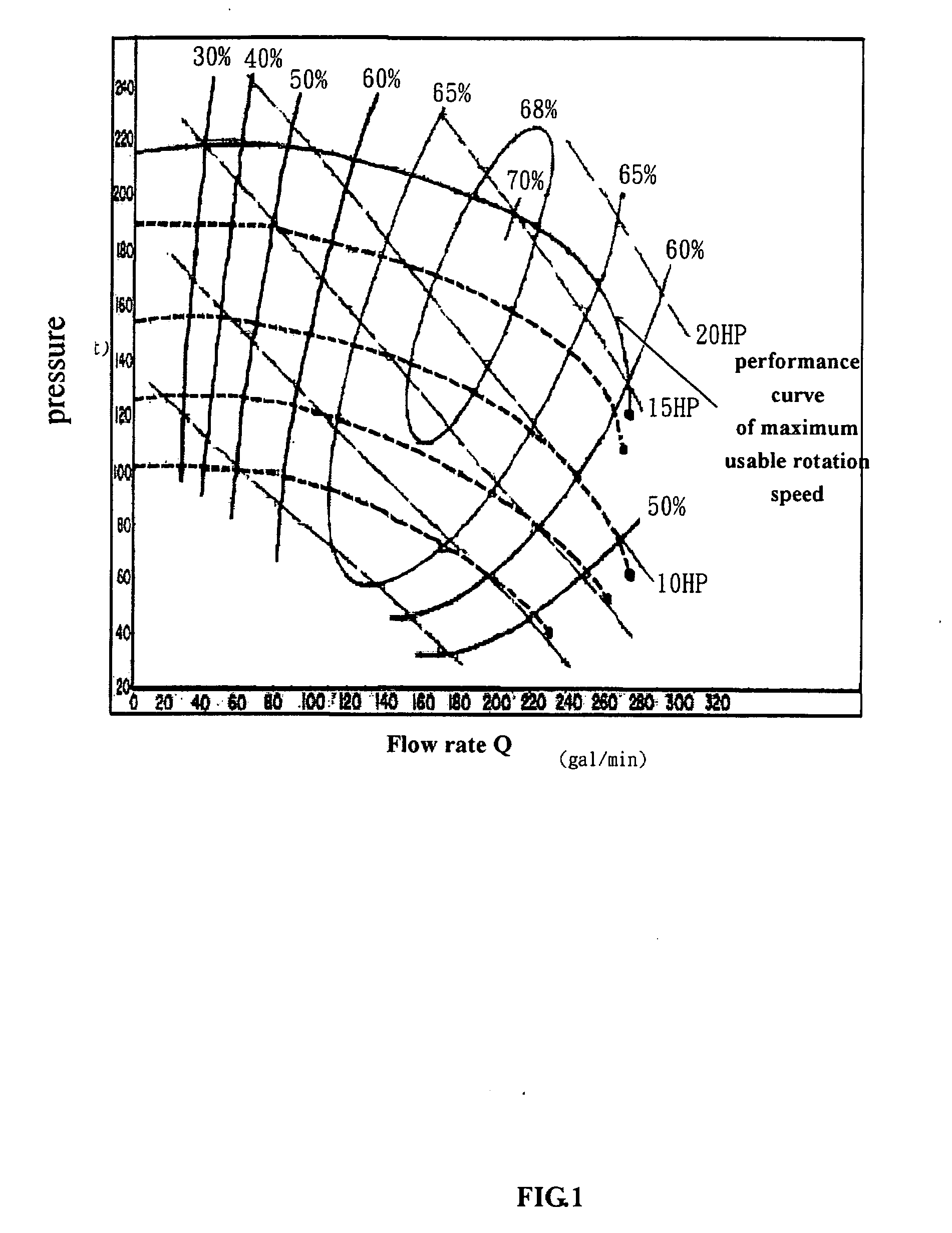
[0042] The embodiment to be discussed below supposes that the flow rate required by the system is QT, and the pressure of the system is a constant pressure PT, and the maximum flow rate a single pump can provides is Q1, and the maximum pressure a single pump can provide is P1. When the system uses multiple pumps, the embodiment also supposes that those pumps are of the same specification of the same manufacturer in principle. From the ...


PUM


Abstract

The present invention discloses a system of energy-efficient and constant-pressure parallel-coupled fluid-transport machines, which can flexibly and massively provide gas and water to every fabrication unit. The system of the present invention comprises: variable-frequency centrifugal fluid-transport machines, pressure gauges, power meters, flow meters, and controllers. The performance curves of the abovementioned system of parallel-coupled fluid-transport machines and the system impedance curves of the loads are analyzed theoretically and built in the controllers together with the equal-efficiency curves provided by the manufacturer. When the system is operating, the data detected by the pressure gauges, power meters, and flow meters are compared with the built-in data to obtain the optimal energy-efficient conditions as the operational criteria of the system of the present invention.

Description

BACKGROUND OF THE INVENTION [0001] 1. Field of the Invention [0002] The present invention relates to a parallel-coupled fluid-transport machinery, particularly to a system of energy-efficient and constant-pressure parallel-coupled fluid-transport machines. [0003] 2. Description of the Related Art [0004] For recent years, owing to the advance of technology, the industrial products are growing precise, delicate and miniature more and more. To mass-produce those precise, delicate and miniature products in low cost, the current high-tech factories grow in scale continuously, and the quality requirements thereof also become more and more strict, which is a challenge for the building companies of the high-tech factory and the facility engineers who maintain the high-tech factory, and which also drives the related personnel to zealously research solutions or develop new technologies to fulfill the requirements. [0005] In the current high-tech factories, it is a basic requirement for fluid-...

Claims


Application Information

Patent Timeline
Patent Type & Authority Applications(United States)
IPC IPC(8): G05D7/00
CPCG05D7/0641F04D15/029
Inventor WANG, CHI-YIHUANG, WEN-CHENGFU, WU-HSIUNG
Owner HUANG WEN CHENG
Why Eureka
Try Eureka